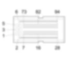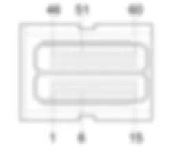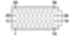

Components - FAP PARTICLE FILTER SYSTEM - Fiat DOBLO 1.9 JTD 8V Fino a 10/2000
| Component code | Description | Reference to the assembly |
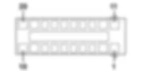
| B001 | JUNCTION UNIT | |
| B2 | JUNCTION UNIT UNDER DASHBOARD | |
| C15 | DASHBOARD EARTH, DRIVER''S SIDE | |
| D004 | FRONT/ENGINE COUPLING | |
| E50 | INSTRUMENT PANEL | |
| H001 | IGNITION SWITCH | |
| K187 | FAP DIFFERENTIAL PRESSURE SENSOR | |
| K189 | UPSTREAM PARTICULATE FILTER TEMPERATURE SENSOR (DPF) | |
| K190 | DOWNSTREAM PARTICULATE FILTER TEMPERATURE SENSOR (DPF) | |
| M001 | BODY COMPUTER | |
| M010 | ENGINE MANAGEMENT ECU |
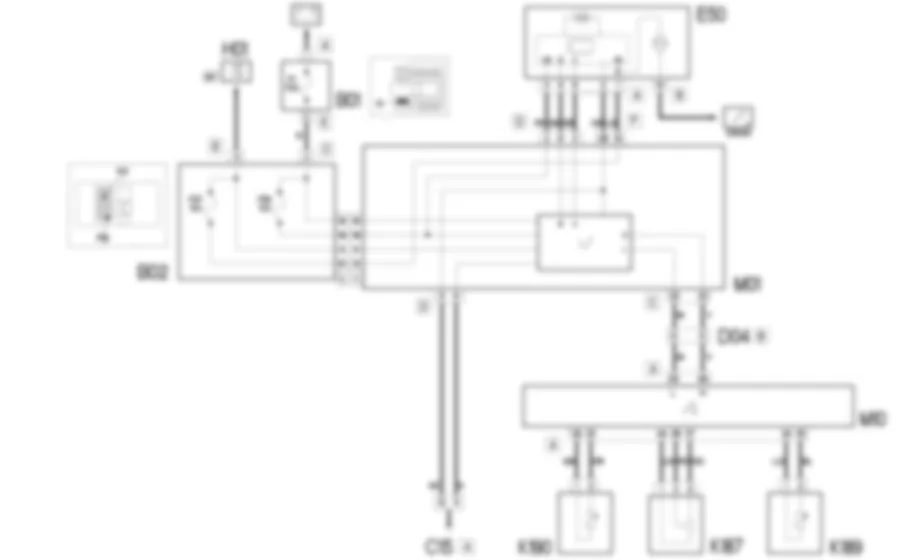
The DPF (Diesel Particulate Filter) is a system designed to keep down the level of particulates in the exhaust systems in diesel engines.The DPF system consists of:- the DPF filter;- sensors and actuators;- specific engine management control unit strategies.Since the filter is an accumulation system, it must be periodically regenerated (cleaned) by burning the particles present in the filter whose quantity is calculated using a control algorithm for the engine management control unit.The engine management control unit uses multiple injections to increase the temperature of the exhaust gases up to around 600°C to burn the particles.The regeneration of the filter takes place by brining the exhaust gases at the DPF intake to a temperature of >580°C and an oxygen content > 5%.The engine management control unit controls the process acting on:- diesel metering (up to 5 injections in the same engine cycle per cylinder);- control of the air (EGR, supercharging pressure).The duration of the regeneration process varies depending on the type of vehicle and the level of blockage.During this stage the specific calibration of the engine guarantees that there is no discontinuity in the torque supplied in relation to normal operation therefore the customer should not be aware of anything and the regeneration stage should be kept activated in all engine operating conditions.The instrument panel provides the information necessary for the management of the filter regeneration process by means of warning lights and messages.The "particle filter blocked" warning light signal indicates that the particle filter needs regeneration and the driving profile does not allow regeneration.If, on the other hand, the system is not capable of carrying out the regeneration, the "engine management system - EOBD failure" warning light will also come on and there will be a message in the display to indicate that the regeneration of the filter is impossible.For further details,
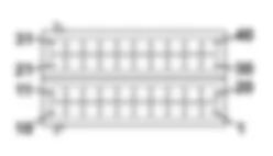
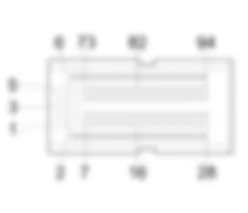
The engine management control unit M10 controls and manages the DPF system with the help of 3 special sensors:- downstream particle filter temperature sensor K190;- upstream particle filter temperature sensor K189;- DPF differential pressure sensor K187.Sensor K190 receives an earth signal from the engine management control unit M10 - pin 33 of connector A - and sends the temperature signal to pin 32 of connector A of M10.Sensor K189 receives an earth signal from the engine management control unit M10 - pin 35 of connector A - and sends the temperature signal to pin 34 of connector A of M10.Sensor K187 receives a power supply and an earth signal from the engine management control unit M10 - pin 44 and 37 of connector A - and sends the pressure signal to pin 36 of connector A of M10.The control unit M10 sends, via the C-CAN - pins 83 and 84 of connector A, the signals useful for the display of the warnings lights and messages in the instrument panel E50. The latter, via the C-CAN/B-CAN communication gateway management by the Body Computer M01, communicates with the system - pins 8 and 9 of connector A - managing the signalling for the management of the filter regeneration process ("particle filter blocked") or by signalling the impossibility of the filter regeneration ("EOBD failure").
 Deutsch
 English
 English
 Español
 Français
 Nederlands
 Русский

