 https://portal-diagnostov.com/license.html
Automotive Electricians Portal FZCO
Automotive Electricians Portal FZCO
https://portal-diagnostov.com/license.html
https://portal-diagnostov.com/license.html
Automotive Electricians Portal FZCO
Automotive Electricians Portal FZCO
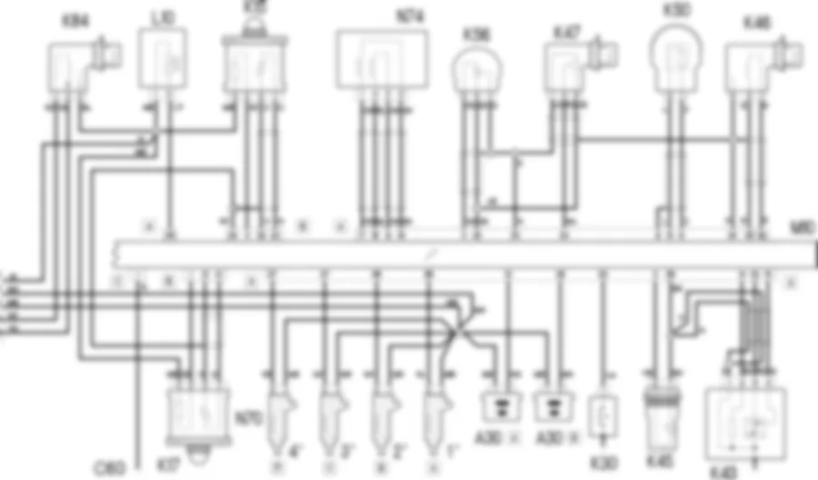
Wiring diagram - PETROL ENGINES ELECTRONIC MANAGEMENT - Fiat DOBLO 1.2 8v Da 10/2000
COMPONENTS - PETROL ENGINES ELECTRONIC MANAGEMENT - Fiat DOBLO 1.2 8v Da 10/2000
| Component code | Name | Assembly reference |
| A30 | Ignition ''coil | |
| B1 | Engine compartment junction unit | - |
| B1 | Engine compartment junction unit | |
| B1 | Engine compartment junction unit | |
| B1 | Engine compartment junction unit | |
| B2 | Junction unit under dashboard | - |
| B2 | Junction unit under dashboard | |
| C15 | Facia earth, driver''s side | - |
| C30 | Left rear earth | - |
| C40 | Earth on engine | - |
| C60 | Injection ECU earth | - |
| D4 | Front/engine coupling | - |
| D36 | Rear right door connection | - |
| D81 | Injector junction | - |
| E50 | Instrument panel | - |
| E50 | Instrument panel | |
| I30 | Brake pedal switch | - |
| I50 | Inertial switch | |
| K15 | Lambda sensor on pre-catalyzer | |
| K17 | Lambda sensor on catalyzer | |
| K30 | Insufficient engine oil pressure (switch) sensor | |
| K39 | Lambda sensor - 2 | - |
| K40 | Lambda sensor | - |
| K43 | Integrated air temperature sensor | |
| K45 | Engine temperature sensor for i.e. | |
| K46 | RPM sensor | |
| K47 | Timing sensor | - |
| K50 | Detonation sensor | - |
| K55 | Accelerator pedal potentiometer | - |
| K56 | Throttle position sensor | 1056A |
| K84 | Speedometer sensor | |
| L10 | Fuel vapour recovery solenoid | |
| M1 | Body computer | - |
| M1 | Body computer | |
| M10 | Engine management ECU | |
| N40 | Fuel pump and sender unit | |
| N70 | Injector | |
| N70 | Injector | |
| N70 | injector | |
| N70 | injector | |
| N74 | Idle actuator | - |
| N75 | Integrated throttle body actuator | |
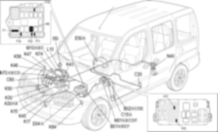
Location of components - PETROL ENGINES ELECTRONIC MANAGEMENT - Fiat DOBLO 1.2 8v Da 10/2000
COMPONENTS - PETROL ENGINES ELECTRONIC MANAGEMENT - Fiat DOBLO 1.2 8v Da 10/2000
| Component code | Name | Assembly reference |
| A30 | Ignition ''coil | |
| B1 | Engine compartment junction unit | - |
| B1 | Engine compartment junction unit | |
| B1 | Engine compartment junction unit | |
| B1 | Engine compartment junction unit | |
| B2 | Junction unit under dashboard | - |
| B2 | Junction unit under dashboard | |
| C15 | Facia earth, driver''s side | - |
| C30 | Left rear earth | - |
| C40 | Earth on engine | - |
| C60 | Injection ECU earth | - |
| D4 | Front/engine coupling | - |
| D36 | Rear right door connection | - |
| D81 | Injector junction | - |
| E50 | Instrument panel | - |
| E50 | Instrument panel | |
| I30 | Brake pedal switch | - |
| I50 | Inertial switch | |
| K15 | Lambda sensor on pre-catalyzer | |
| K17 | Lambda sensor on catalyzer | |
| K30 | Insufficient engine oil pressure (switch) sensor | |
| K39 | Lambda sensor - 2 | - |
| K40 | Lambda sensor | - |
| K43 | Integrated air temperature sensor | |
| K45 | Engine temperature sensor for i.e. | |
| K46 | RPM sensor | |
| K47 | Timing sensor | - |
| K50 | Detonation sensor | - |
| K55 | Accelerator pedal potentiometer | - |
| K56 | Throttle position sensor | 1056A |
| K84 | Speedometer sensor | |
| L10 | Fuel vapour recovery solenoid | |
| M1 | Body computer | - |
| M1 | Body computer | |
| M10 | Engine management ECU | |
| N40 | Fuel pump and sender unit | |
| N70 | Injector | |
| N70 | Injector | |
| N70 | injector | |
| N70 | injector | |
| N74 | Idle actuator | - |
| N75 | Integrated throttle body actuator | |
Description - PETROL ENGINES ELECTRONIC MANAGEMENT - Fiat DOBLO 1.2 8v Da 10/2000
An electronic management system supervises and governs all engine parameters. It optimises performance and fuel consumption by responding in real time to different service conditions.The system is managed by a single control unit which controls both the ignition and the injection.The system uses signals received from numerous sensors to control actuators. It is connected to the following systems:fuel supply;air supply system;engine cooling;exhaust with catalytic converter;fuel vapour recirculation.
This version of the system also includes the EOBD (European On Board Diagnosis) system - conforming to Directive 98/69/CE (EURO 3) - permits continuous diagnosis of the components - associated with emissions, and by the warning light coming on, indicates any deterioration of these components.Among other things, the system diagnoses:the catalytic converter, which in the case of a malfunction does not convert the pollutants produced by the engine;the Lambda sensors (oxygen sensors);the lack of combustion, so unburnt fuel reaches the catalyzer where the thermal conversion reactions cause a sudden increase in temperature, damaging the catalyzer.
This autodiagnostic system also produces a signal for switching on the (amber yellow) ''injection/EOBD failure'' warning light in the instrument panel.The system is also controlled by means of a relay located in the junction unit in the engine compartment. The supply lines for the engnie management control unit and the various system components (sensors and actuators) are protected by a special fuse, also located in the above mentioned box.
Functional description - PETROL ENGINES ELECTRONIC MANAGEMENT - Fiat DOBLO 1.2 8v Da 10/2000
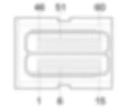
The engine management control unit M10 monitors and controls the entire electronic ignition and injection system.It is supplied directly by the battery at pin 4 of connector B via the line protected by fuse F18 , housed in the engine compartment junction unit B1 .The supply controlled by the ignition (15/54) reaches pin 17 of connector B from the line protected by fuse F16 also housed in the engine compartment junction unit B01 , whilst pin 1 of connector C is earthed.The control unit M10 energizes the relay R9, via a control signal coming out of pin 6 of connector B, which delivers the supply via two different lines protected by fuses F11 and F22 to the:injectors N70 ;ignition coil A30 ;vapour recovery solenoid valve L10 ;speedometer sensor K84 ;Lambda sensors K15 and K17;electric fuel pump N40.
The relay R9 is supplied directly from the battery at pin 1 of connector A of B01 , while the coil receives an ignition-operated supply (15/54) from the line protected by fuse F16;The electric fuel pump N40 is earthed through the inertia switch I50 which, in the case of an impact, cuts off the circuit and stops the supply of fuel.The idle actuator N74 regulates the by-pass line. It is controlled by the control unit M10 through the signals from pins 9 and 19, 17 and 18 of connector A. The fuel vapour recovery solenoid L10 allows fuel vapours to pass through to the engine intake where they join the mixture entering the combustion chamber. The valve L10 , supplied by the main relay R9 , is opened by the control unit when the engine is loaded by a signal from pin 26 of connector A of M10 .The injectors N70 are controlled by the control unit as well as the relay R9 also through special signals sent from pins 28, 36, 37 and 27 to the actual injectors.The control unit M10 also controls the coil A30 through the signals for the coil primary winding, whilst the secondary winding sends the impulse to the spark plugs (from pin 38 of the control unit for the pair of cylinders 1 & 4 and from pin 10 for cylinders 2 & 3).The engine management control unit M10 receives signals from the various sensors in order to monitor all engine service conditions.The rpm sensor K46 sends information, through an alternating frequency sent to pins 25 (positive) and 35 (negative) of the control unit M10 via the screened line (pin 34), concerning the engine speed;The timing sensor K47 provides information on the engine timing to the control unit through a signal sent to pins 24 and 32 (negative) of the control unit M10 via the screened line (pin 34);The air temperature and pressure sensor K43 receives a signal corresponding to the temperature from pin 14 of connector A of the engine control unit M10 at pins 13 and 22 concerning the supply and the signal which concerns the pressure; these signals are screened appropriately;The throttle position sensor K56 is supplied at 5 V from pin 32 of connector A of M10 and receives a reference earth from pin 20 connector A; it sends, through a potentiometer, a signal proportional to the degree of opening of the butterfly to pin 3 of connector A of M10 ;the engine temperature sensor K45 , receives a reference earth from pin 29 of the control unit M10 and supplies a signal proportional to the temperature of the engine coolant to pin 5 of the control unit;the detonation sensor K50 provides information concerning the onset of detonation in the combustion chamber through alternating signals: it sends two signals to pins 6 (positive) and 15 (negative ) of connector A of M10 ; these signals are also suitably screened (pin 8 connector A);the heated Lambda sensor K15 provides the control unit M10 with information concerning the correct composition of the air/fuel mixture: the signal is exchangd with pin 22 (positive) and pin 32 (negative) of connector B of the control uni both suitably screened (pin 34). The sensor K15 is heated by a resistor in order to ensure it works efficiently even when cold. the resistance is supplied by the main relay R9 through the line protected by fuse F11 ; the control unit sends an earth signal from pin 11 of connector B;the 2nd Lambda sensor K17 through pin 1 and the screened line to pins 21 and 31 of the control unit M10;Pin 23 of connector A of the engine control unit receives the signal for the insufficient engine oil pressure switch K30 .
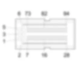
The injection control unit M10 exchanges information with the body computer M01 concerning the correct operation of the system via the CAN line from pins 20 and 29 of connector B of the control unit to pins 37 and 36 of connector C of the body computer. The diagnostic line from pin 16 of the control unit to pin 10 of the body computer also travels between the two systems. A failure in the injection system and/or the incorrect emission of exhaust gases (EOBD) is highlighted by the amber yellow warning light in the instrument panel E50, the management of irregularities is therefore controlled by the body computer logic.The body computer M01 also receives values from the speedometer sensor K84 at pins 15 and 17 of connector C.The control unit M10 is connected to the air conditioning system via pins 12, 27, 28 and 38. This makes it possible to adjust the engine idle speed as the load increases each time the compressor is switched on or to switch off the compressor in the case of high engine speed or load conditions.The control unit also controls the engine cooling system: pins 8 and 18 control the engagement of the relevant fan.JUNCTION UNIT
B001A
B001B
B001C
B001C
B001C
B001C
B001C
B001D
B001E
B001F
B001F
B001F
B001F
B001F
B1A
B1A
B1B
B1C
B1C
B1C
B1C
B1C
B1C
B1C
B1C
B1D
B1E
B1E
B1F
B1F
B1F
B1F
B1F
B1F
JUNCTION UNIT UNDER DASHBOARD
B002A
B002A
B002A
B002A
B002A
B002C
B002D
B002D
B002E
B002E
B002E
B002F
B002G
B002G
B2A
B2A
B2A
B2A
B2A
B2C
B2D
B2D
B2D
B2E
B2E
B2E
B2E
B2F
B2G
DASHBOARD EARTH, DRIVER''S SIDE
C015A
C015A
C015C
C15A
C15A
C15B
C15C
ENGINE EARTH
C040
C040A
C040B
C40
C40
C40A
C40B
FRONT/ENGINE COUPLING
D4A
D4A
D4A
D4A
D4A
D4A
D4A
D4A
D4A
D4A
D4B
D4B
D4B
D4B
D4B
D4B
D4B
D4B
D4B
D4B
D004A
D004A
D004A
D004A
D004A
D004A
D004A
D004A
D004B
D004B
D004B
D004B
D004B
D004B
D004B
D004B
REAR/RIGHT REAR DOOR COUPLING
D36A
D36A
D36B
INSTRUMENT PANEL
E050A
E050A
E050B
E050B
E050B
E50A
E50A
E50B
E50B
E50B
E50B
E50B
ENGINE OIL PRESSURE SENSOR (SWITCH)
K30
K30
K30
K30
K30
K30
K30
K030
K030
K030
K030
LAMBDA SENSOR
K40
K40
K040
K040
ENGINE COOLANT TEMPERATURE SENSOR
K45
K45
K45
K45
K45
K45
K45
THROTTLE POSITION SENSOR
K56
K56
K56
K056
SPEEDOMETER SENSOR
K84
K84
K84
K84
K84
K84
K084
K084
K084
K084
K084
BODY COMPUTER
M1A
M1A
M1A
M1A
M1C
M1D
M1E
M1F
M001A
M001A
M001A
M001A
M001A
M001C
M001C
M001C
M001D
M001D
M001E
M001E
M001F
M001F
ENGINE MANAGEMENT ECU
M10B
M10B
M10B
M10B
M10B
M10B
M10C
M10C
M10C
M010A
M010A
M010A
M010A
M010A
M010A
M010B
M010B
M010B
M010B
M010B
M010B
M010C
M010C
M10
M10A
M10A
M10A
M10A
M10A
M10A
M10B
FUEL PUMP AND LEVEL GAUGE
N040
N040
N040
N40
N40
INJECTOR
N070A
N070A
N070A
N070A
N070B
N070B
N070B
N070B
N070C
N070C
N070C
N070C
N070D
N070D
N070D
N070D
N70A
N70A
N70A
N70A
N70A
N70A
N70A
N70A
N70A
N70B
N70B
N70B
N70B
N70B
N70C
N70C
N70C
N70C
N70C
N70D
N70D
N70D
N70D
N70D
IDLE ACTUATOR
N074
N74
N74
N74


 Deutsch
 English
 English
 Español
 Français
 Nederlands
 Русский


