ENGINE PERFORMANCE
5.0L
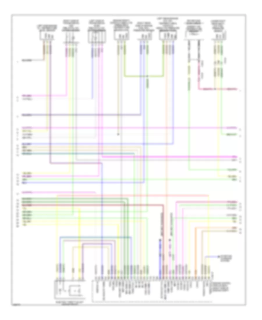
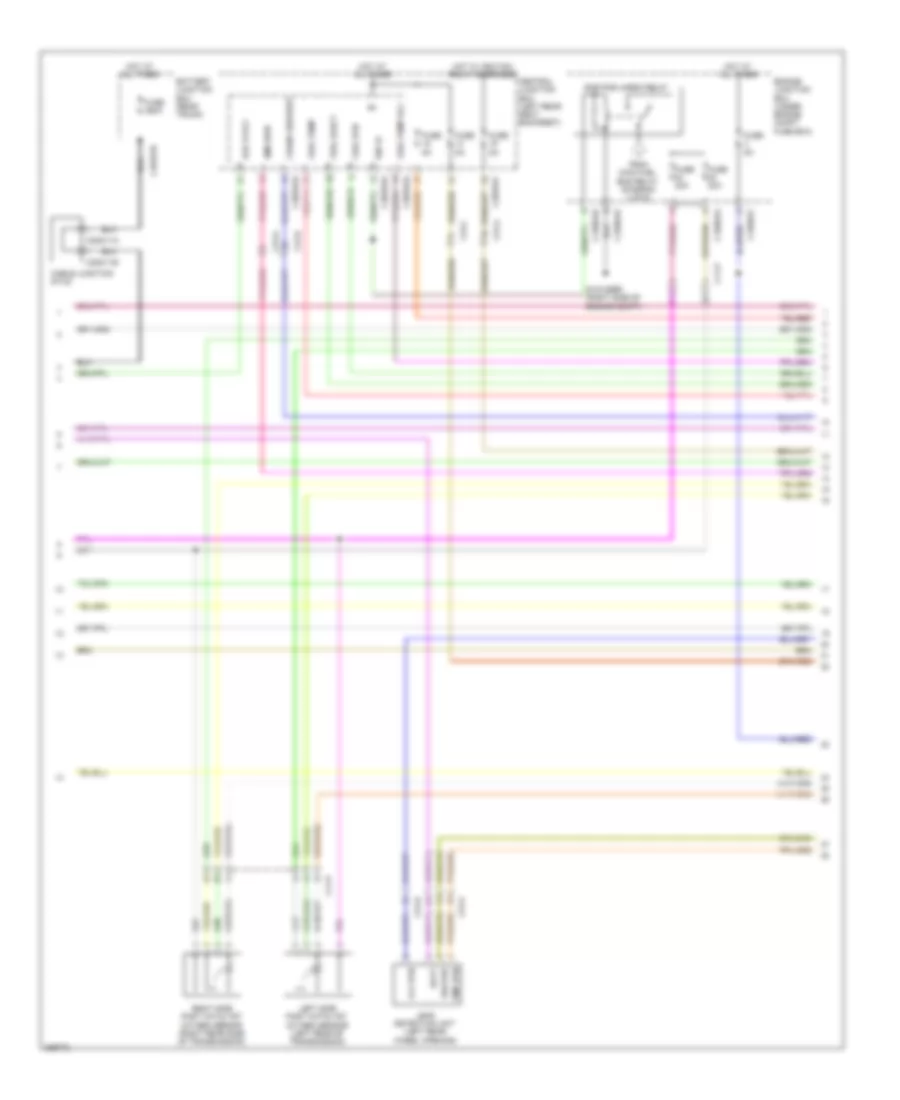
5.0L, Engine Performance Wiring Diagram (1 of 6) for Jaguar XJ Supercharged 2012


List of elements for 5.0L, Engine Performance Wiring Diagram (1 of 6) for Jaguar XJ Supercharged 2012:
- (engine right side) fuel injector 1
- (engine right side) fuel injector 2
- (engine right side) fuel injector 3
- (engine right side) fuel injector 4
- (left side engine) fuel injector 5
- (left side engine) fuel injector 6
- (left side engine) fuel injector 7
- (left side engine) fuel injector 8
- Air temp sens gnd
- C11-a
- C11-p
- C1e117
- Cam ex a
- Cam ex b
- Cam in a
- Cam in b
- Cam sens a gnd
- Cam sens a sply
- Cam sens b gnd
- Cam sens b sply
- Capacitor (right rear side of engine)
- Coolant temp 2
- Crank sens
- Crank sens gnd
- Ctrl
- Engine control module (ecm) (right side of engine compt)
- Front bank knock sensor 2 (engine top)
- Fuel press sens
- Fuel pump 1
- Fuel pump 2
- Gnd
- Htr ctrl a upstream
- Htr ctrl b upstream
- Ign
- Ignition 1b
- Ignition 2a
- Ignition 2b
- Ignition 3a
- Ignition 3b
- Ignition 4a
- Ignition 4b
- Ignition coil 1 (engine right side)
- Ignition coil 3 (engine right side)
- Ignition coil 5 (engine right side)
- Ignition coil 7 (engine right side)
- Inj 1a common
- Inj 1b common
- Inj 2a
- Inj 2a common
- Inj 2b
- Inj 2b common
- Inj 3a
- Inj 3a common
- Inj 3b common
- Inj 4a
- Inj 4a common
- Inj 4b
- Inj 4b common
- Inlet air temp b
- Knock sens 1a
- Knock sens 1a gnd
- Knock sens 1b
- Knock sens 1b gnd
- Knock sens 2a
- Knock sens 2a gnd
- Knock sens 2b
- Knock sens 2b gnd
- Maf sens a gnd
- Maf sens b gnd
- Map sens gnd
- Oil quality sens gnd
- Pi080 (engine right front)
- Rear bank knock sensor 2 (engine top)
- Sen gnd
- Sens 5v sply
- Sens gnd
- Tmap press sens
- Tps 5v feed
- Uhego a constant
- Uhego a variable
- Uhego b constant
- Uhego b variable
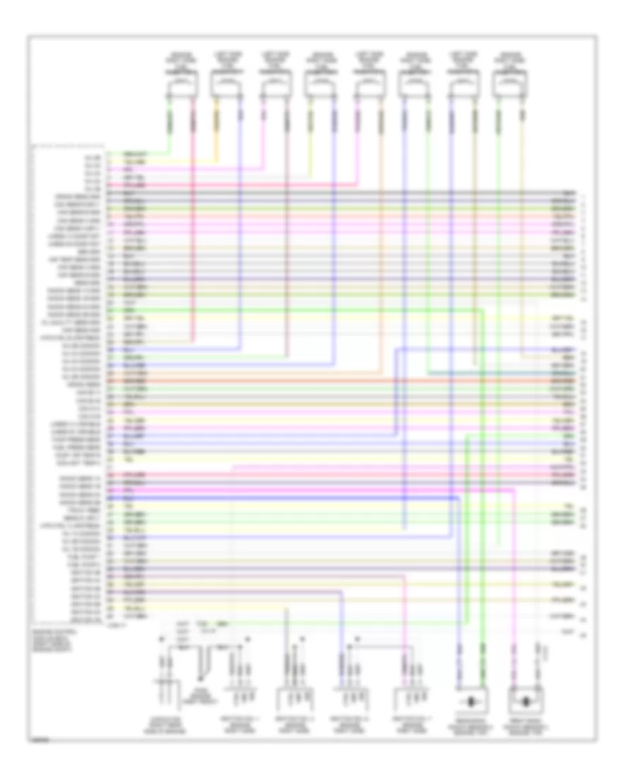
5.0L, Engine Performance Wiring Diagram (2 of 6) for Jaguar XJ Supercharged 2012
List of elements for 5.0L, Engine Performance Wiring Diagram (2 of 6) for Jaguar XJ Supercharged 2012:
- (engine front left) inlet camshaft position sensor (bank 2)
- (engine front) maf/iat sensor (bank 1)
- (engine front) maf/iat sensor (bank 2)
- (engine front) outlet camshaft position sensor (bank 1)
- (engine left front) outlet camshaft position sensor (bank 2)
- (engine top) front bank knock sensor 1
- (engine top) rear bank knock sensor 1
- (left side engine) crankshaft position (ckp)/ sensor
- (right front engine) inlet camshaft position sensor (bank 1)
- C11-a
- C11-p
- Ctrl
- Engine coolant temperature sensor 1 (right rear side of engine)
- Engine coolant temperature sensor 2 (engine front)
- Gnd
- High pressure fuel pump 1 (engine right side)
- High pressure fuel pump 2 (engine right side)
- Iat gnd
- Iat out
- Iat output
- Ign
- Ignition coil 2 (left side engine)
- Ignition coil 4 (left side engine)
- Ignition coil 6 (left side engine)
- Ignition coil 8 (left side engine)
- Maf sens
- Nca
- Pi082 (engine left front)
- Pwr
- Pwr 5v
- Sens
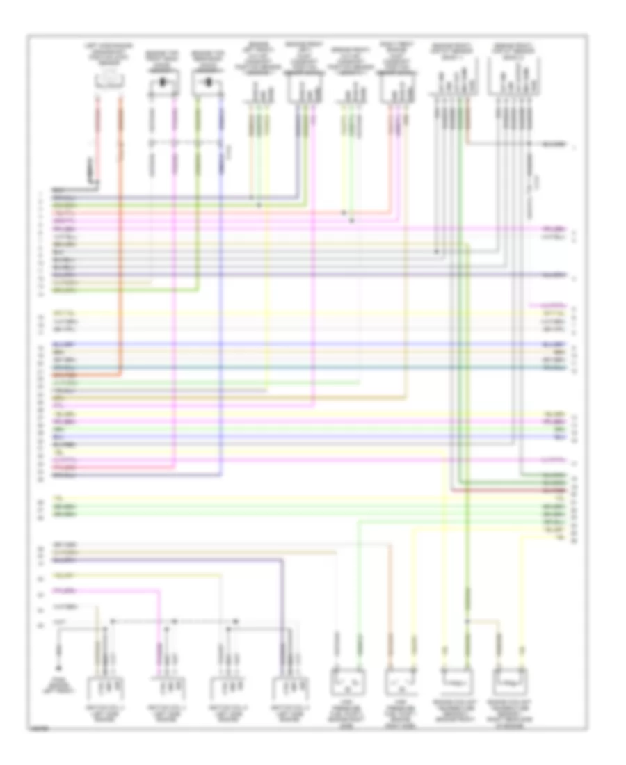
5.0L, Engine Performance Wiring Diagram (3 of 6) for Jaguar XJ Supercharged 2012
List of elements for 5.0L, Engine Performance Wiring Diagram (3 of 6) for Jaguar XJ Supercharged 2012:
- (engine front) manifold absolute pressure & temperature sensor (map)
- (info not available)
- (left rear engine) (5.0l sc) temperature & manifold absolute pressure sensor (tmap)
- (left side engine) oil temperature level sensor
- (left side of transmission) even pre catalyst oxygen sensor
- (right rear side of engine) fuel rail pressure sensor
- (right side of transmission) odd pre catalyst oxygen sensor
- (under right rear seat) low fuel pressure sensor
- +5v
- Active ext vlv
- Ambient air temperature sensor
- C11-p
- C1e117
- C31-a
- C31-d
- C3a-a
- Coolant temp
- Cps a
- Cps b
- Driver side door mirror
- E box fan
- Electric throttle unit (engine front)
- Engine control module (ecm) (right side of engine compt)
- Fuel pump 1
- Fuel pump 2
- Gnd
- Ignitor 1a
- Imtv
- Inj 1a
- Inj 1b
- Inj 3b
- Inlet air temp a
- Lin a
- Maf sens a
- Maf sens b
- Map sens
- Nca
- Oil quality sens
- Purge valve
- Sig
- Starting/ charging system
- Temp
- Temp sens
- Throttle +
- Throttle -
- Tps gnd
- Tps1
- Tps2
- Vfs ex b
- Vfs in a
- Vfs in b
- Vfsex a
- Vout
- Vref
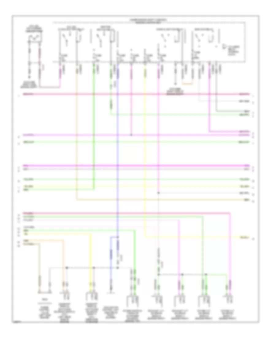
5.0L, Engine Performance Wiring Diagram (4 of 6) for Jaguar XJ Supercharged 2012
List of elements for 5.0L, Engine Performance Wiring Diagram (4 of 6) for Jaguar XJ Supercharged 2012:
- (5.0l sc) air charger coolant pump
- (5.0l sc) ic coolant pmp relay
- (under engine compt fuse box) engine junction box
- C11-a
- C11-f
- C11-p
- C1bb01c
- C1bb01e
- C1bb01f
- C1bb01j
- C1bb01k
- C1bb01l
- C31-a
- Camshaft profile switching solenoid (bank 1) (5.0l) (rear side of engine)
- Camshaft profile switching solenoid (bank 2) (5.0l) (left rear side of engine)
- Cooling fan control unit (center of front bumper)
- Ctrl
- Dmr pcb ignition relay
- Ems main relay
- Exhaust vvt solenoid (bank 1) (engine front)
- Exhaust vvt solenoid (bank 2) (engine front)
- Fuse 10a
- Fuse 15a
- Fuse 20a
- Fuse 5a
- G1d125br (right side of engine compt)
- G1d131br (right side engine compt)
- Intake manifold tuning or symposer solenoid (engine top)
- Intake vvt solenoid (bank 1) (engine front)
- Intake vvt solenoid (bank 2) (engine front)
- Micro & ignition relay
- Nca
- Purge control valve (left side engine)
- Sply
- To uhego relay (diagram 5 of 6)
5.0L, Engine Performance Wiring Diagram (5 of 6) for Jaguar XJ Supercharged 2012
List of elements for 5.0L, Engine Performance Wiring Diagram (5 of 6) for Jaguar XJ Supercharged 2012:
- Batt
- Battery junction box (rear trunk)
- C11-p
- C1bb01a
- C1bb01e
- C1bb01f
- C1bb01k
- C31-a
- C31-b
- C31-c
- C3bp01e
- C3bp01f
- C3bp01g
- C3dc11a
- C3dc11b
- C4bf01b
- Cable junction stud
- Central junction box (left rear seat backrest)
- Crank request
- Dme pcb uhego relay
- Ejb 15 rly
- Ems ewu
- Engine junction box (under engine compt fuse box)
- From main fuel ems relay (diagram 4 of 6)
- Fuel eject
- Fuel pump
- Fuel pump rly
- Fuel rtn
- Fuse 20a
- Fuse 250a
- Fuse 5a
- G1d125br (right side of engine compt)
- Heater
- Hot at all times
- Hot w/ ignition relay energized
- Ign 15
- Leak detection unit (left rear wheel opening)
- Left side post catalyst oxygen sensor (left rear of transmission)
- Pmp rtn
- Right side post catalyst oxygen sensor (right rear side of transmission)
- Vlv rtn
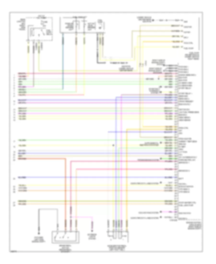
5.0L, Engine Performance Wiring Diagram (6 of 6) for Jaguar XJ Supercharged 2012
List of elements for 5.0L, Engine Performance Wiring Diagram (6 of 6) for Jaguar XJ Supercharged 2012:
- (right side of engine compt) g1d124al
- (right side of engine compt) g1d124ar
- (under vehicle center rear) g4d197as
- 5v ref+
- Accelerator pedal position sensor (left foot well)
- Active level sender unit
- Ambient temp sens
- Ap1
- Ap2
- Ap5v
- B bank sens gnd 2
- Batt
- Brake pedal switch (brake pedal bracket)
- Brake sw 1
- Brake sw 2
- C1e120b
- C31-a
- C4br01b
- C4br01c
- Computer data lines system
- Cooling fans system
- Cov
- Crank request
- Ecm pwr
- Ems ewu
- Ems main rly
- Engine control module (ecm) (right side of engine compt)
- Etb motor pwr
- Exterior lights system
- Fpdm ctrl
- Fpdm monitor
- Fuel leak pump
- Fuel pump
- Fuel pump driver module (under vehicle right rear)
- Fuel pump relay
- Fuel tank unit
- Fuse 30a
- G1d122bs (left side engine compt)
- G4d197as (under vehicle center rear)
- Gnd
- Hego sens a
- Hego sens b
- Hot at all times
- Hs can h
- Hs can l
- Htr hego a
- Htr hego b
- Ignition sw
- Int waterpump rly
- Low fuel press sens
- Monitor
- Motor -
- Nca
- Ox sens a gnd
- Ox sens b gnd
- Park/neutral sw
- Passive level sender unit
- Pump heater ctrl
- Pwm ctrl
- Pwr gnd 1
- Pwr gnd 2
- Pwr gnd 3
- Rad fan pwm
- Rear junction box (right side trunk)
- Sens gnd
- Sens gnd 2
- Sply
- Srs sig
- Start relay +
- Start relay -
- Starting/ charging system
- Transmissions system
- Vvt pwr
5.0L SC
5.0L SC, Engine Performance Wiring Diagram (1 of 6) for Jaguar XJ Supercharged 2012
List of elements for 5.0L SC, Engine Performance Wiring Diagram (1 of 6) for Jaguar XJ Supercharged 2012:
- (engine right side) fuel injector 1
- (engine right side) fuel injector 2
- (engine right side) fuel injector 3
- (engine right side) fuel injector 4
- (left side engine) fuel injector 5
- (left side engine) fuel injector 6
- (left side engine) fuel injector 7
- (left side engine) fuel injector 8
- Air temp sens gnd
- C11-a
- C11-p
- C1e117
- Cam ex a
- Cam ex b
- Cam in a
- Cam in b
- Cam sens a gnd
- Cam sens a sply
- Cam sens b gnd
- Cam sens b sply
- Capacitor (right rear side of engine)
- Coolant temp 2
- Crank sens
- Crank sens gnd
- Ctrl
- Engine control module (ecm) (right side of engine compt)
- Front bank knock sensor 2 (engine top)
- Fuel press sens
- Fuel pump 1
- Fuel pump 2
- Gnd
- Htr ctrl a upstream
- Htr ctrl b upstream
- Ign
- Ignition 1b
- Ignition 2a
- Ignition 2b
- Ignition 3a
- Ignition 3b
- Ignition 4a
- Ignition 4b
- Ignition coil 1 (engine right side)
- Ignition coil 3 (engine right side)
- Ignition coil 5 (engine right side)
- Ignition coil 7 (engine right side)
- Inj 1a common
- Inj 1b common
- Inj 2a
- Inj 2a common
- Inj 2b
- Inj 2b common
- Inj 3a
- Inj 3a common
- Inj 3b common
- Inj 4a
- Inj 4a common
- Inj 4b
- Inj 4b common
- Inlet air temp b
- Knock sens 1a
- Knock sens 1a gnd
- Knock sens 1b
- Knock sens 1b gnd
- Knock sens 2a
- Knock sens 2a gnd
- Knock sens 2b
- Knock sens 2b gnd
- Maf sens a gnd
- Maf sens b gnd
- Map sens gnd
- Oil quality sens gnd
- Pi080 (engine right front)
- Rear bank knock sensor 2 (engine top)
- Sen gnd
- Sens 5v sply
- Sens gnd
- Tmap press sens
- Tps 5v feed
- Uhego a constant
- Uhego a variable
- Uhego b constant
- Uhego b variable
5.0L SC, Engine Performance Wiring Diagram (2 of 6) for Jaguar XJ Supercharged 2012
List of elements for 5.0L SC, Engine Performance Wiring Diagram (2 of 6) for Jaguar XJ Supercharged 2012:
- (engine front left) inlet camshaft position sensor (bank 2)
- (engine front) maf/iat sensor (bank 1)
- (engine front) maf/iat sensor (bank 2)
- (engine front) outlet camshaft position sensor (bank 1)
- (engine left front) outlet camshaft position sensor (bank 2)
- (engine top) front bank knock sensor 1
- (engine top) rear bank knock sensor 1
- (left side engine) crankshaft position (ckp)/ sensor
- (right front engine) inlet camshaft position sensor (bank 1)
- C11-a
- C11-p
- Ctrl
- Engine coolant temperature sensor 1 (right rear side of engine)
- Engine coolant temperature sensor 2 (engine front)
- Gnd
- High pressure fuel pump 1 (engine right side)
- High pressure fuel pump 2 (engine right side)
- Iat gnd
- Iat out
- Iat output
- Ign
- Ignition coil 2 (left side engine)
- Ignition coil 4 (left side engine)
- Ignition coil 6 (left side engine)
- Ignition coil 8 (left side engine)
- Maf sens
- Nca
- Pi082 (engine left front)
- Pwr
- Pwr 5v
- Sens
5.0L SC, Engine Performance Wiring Diagram (3 of 6) for Jaguar XJ Supercharged 2012
List of elements for 5.0L SC, Engine Performance Wiring Diagram (3 of 6) for Jaguar XJ Supercharged 2012:
- (engine front) manifold absolute pressure & temperature sensor (map)
- (info not available)
- (left rear engine) (5.0l sc) temperature & manifold absolute pressure sensor (tmap)
- (left side engine) oil temperature level sensor
- (left side of transmission) even pre catalyst oxygen sensor
- (right rear side of engine) fuel rail pressure sensor
- (right side of transmission) odd pre catalyst oxygen sensor
- (under right rear seat) low fuel pressure sensor
- +5v
- Active ext vlv
- Ambient air temperature sensor
- C11-p
- C1e117
- C31-a
- C31-d
- C3a-a
- Coolant temp
- Cps a
- Cps b
- Driver side door mirror
- E box fan
- Electric throttle unit (engine front)
- Engine control module (ecm) (right side of engine compt)
- Fuel pump 1
- Fuel pump 2
- Gnd
- Ignitor 1a
- Imtv
- Inj 1a
- Inj 1b
- Inj 3b
- Inlet air temp a
- Lin a
- Maf sens a
- Maf sens b
- Map sens
- Nca
- Oil quality sens
- Purge valve
- Sig
- Starting/ charging system
- Temp
- Temp sens
- Throttle +
- Throttle -
- Tps gnd
- Tps1
- Tps2
- Vfs ex b
- Vfs in a
- Vfs in b
- Vfsex a
- Vout
- Vref
5.0L SC, Engine Performance Wiring Diagram (4 of 6) for Jaguar XJ Supercharged 2012
List of elements for 5.0L SC, Engine Performance Wiring Diagram (4 of 6) for Jaguar XJ Supercharged 2012:
- (5.0l sc) air charger coolant pump
- (5.0l sc) ic coolant pmp relay
- (under engine compt fuse box) engine junction box
- C11-a
- C11-f
- C11-p
- C1bb01c
- C1bb01e
- C1bb01f
- C1bb01j
- C1bb01k
- C1bb01l
- C31-a
- Camshaft profile switching solenoid (bank 1) (5.0l) (rear side of engine)
- Camshaft profile switching solenoid (bank 2) (5.0l) (left rear side of engine)
- Cooling fan control unit (center of front bumper)
- Ctrl
- Dmr pcb ignition relay
- Ems main relay
- Exhaust vvt solenoid (bank 1) (engine front)
- Exhaust vvt solenoid (bank 2) (engine front)
- Fuse 10a
- Fuse 15a
- Fuse 20a
- Fuse 5a
- G1d125br (right side of engine compt)
- G1d131br (right side engine compt)
- Intake manifold tuning or symposer solenoid (engine top)
- Intake vvt solenoid (bank 1) (engine front)
- Intake vvt solenoid (bank 2) (engine front)
- Micro & ignition relay
- Nca
- Purge control valve (left side engine)
- Sply
- To uhego relay (diagram 5 of 6)
5.0L SC, Engine Performance Wiring Diagram (5 of 6) for Jaguar XJ Supercharged 2012
List of elements for 5.0L SC, Engine Performance Wiring Diagram (5 of 6) for Jaguar XJ Supercharged 2012:
- Batt
- Battery junction box (rear trunk)
- C11-p
- C1bb01a
- C1bb01e
- C1bb01f
- C1bb01k
- C31-a
- C31-b
- C31-c
- C3bp01e
- C3bp01f
- C3bp01g
- C3dc11a
- C3dc11b
- C4bf01b
- Cable junction stud
- Central junction box (left rear seat backrest)
- Crank request
- Dme pcb uhego relay
- Ejb 15 rly
- Ems ewu
- Engine junction box (under engine compt fuse box)
- From main fuel ems relay (diagram 4 of 6)
- Fuel eject
- Fuel pump
- Fuel pump rly
- Fuel rtn
- Fuse 20a
- Fuse 250a
- Fuse 5a
- G1d125br (right side of engine compt)
- Heater
- Hot at all times
- Hot w/ ignition relay energized
- Ign 15
- Leak detection unit (left rear wheel opening)
- Left side post catalyst oxygen sensor (left rear of transmission)
- Pmp rtn
- Right side post catalyst oxygen sensor (right rear side of transmission)
- Vlv rtn
5.0L SC, Engine Performance Wiring Diagram (6 of 6) for Jaguar XJ Supercharged 2012
List of elements for 5.0L SC, Engine Performance Wiring Diagram (6 of 6) for Jaguar XJ Supercharged 2012:
- (right side of engine compt) g1d124al
- (right side of engine compt) g1d124ar
- (under vehicle center rear) g4d197as
- 5v ref+
- Accelerator pedal position sensor (left foot well)
- Active level sender unit
- Ambient temp sens
- Ap1
- Ap2
- Ap5v
- B bank sens gnd 2
- Batt
- Brake pedal switch (brake pedal bracket)
- Brake sw 1
- Brake sw 2
- C1e120b
- C31-a
- C4br01b
- C4br01c
- Computer data lines system
- Cooling fans system
- Cov
- Crank request
- Ecm pwr
- Ems ewu
- Ems main rly
- Engine control module (ecm) (right side of engine compt)
- Etb motor pwr
- Exterior lights system
- Fpdm ctrl
- Fpdm monitor
- Fuel leak pump
- Fuel pump
- Fuel pump driver module (under vehicle right rear)
- Fuel pump relay
- Fuel tank unit
- Fuse 30a
- G1d122bs (left side engine compt)
- G4d197as (under vehicle center rear)
- Gnd
- Hego sens a
- Hego sens b
- Hot at all times
- Hs can h
- Hs can l
- Htr hego a
- Htr hego b
- Ignition sw
- Int waterpump rly
- Low fuel press sens
- Monitor
- Motor -
- Nca
- Ox sens a gnd
- Ox sens b gnd
- Park/neutral sw
- Passive level sender unit
- Pump heater ctrl
- Pwm ctrl
- Pwr gnd 1
- Pwr gnd 2
- Pwr gnd 3
- Rad fan pwm
- Rear junction box (right side trunk)
- Sens gnd
- Sens gnd 2
- Sply
- Srs sig
- Start relay +
- Start relay -
- Starting/ charging system
- Transmissions system
- Vvt pwr

 Čeština
 Dansk
Dansk Deutsch
 Ελληνικά
 English
 English
 Español
 Suomi
Suomi Français
 Français
 עברית
עברית Hrvatski
 Magyar
 Italiano
 日本語
日本語 한국어
한국어 Nederlands
 Polski
 Português
 Português
 Română
 Русский
 Slovenčina
 Slovenščina
 Svenska
 中文 (中国)