ANTI-LOCK BRAKES
Anti-lock Brake Wiring Diagrams for Hyundai Accent GL 1997
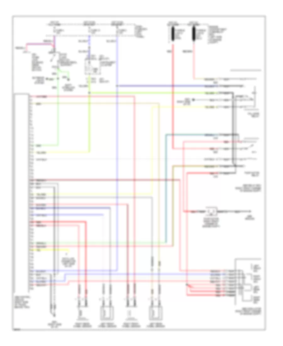
List of elements for Anti-lock Brake Wiring Diagrams for Hyundai Accent GL 1997:
- (gt) (exc gt)
- Abs control module (right side of trunk, behind trim)
- Abs ground
- Abs ind
- Abs modulator (right front corner of engine compt)
- Abs relay box (right front corner of engine compt)
- Dash fuse box (left kick panel)
- Data link connector (left side of i/p)
- E05
- Engine compartment fuse/relay box (left side of engine compt)
- Exterior lights system
- Fail safe relay
- Fuse 10 10a
- Fuse 2 10a
- Fuse 4 15a
- Fusible link g 30a (pnk)
- G201 (right side of i/p)
- Hot at all times
- Hot in on or start
- I07-2
- I08-1
- I08-2
- Instrument cluster
- Key inter- lock solenoid (near igntion switch)
- Left front sol
- Left front wheel sensor
- Left rear sol
- Left rear wheel sensor
- M79
- Nca
- Pump motor (right front corner of engine compt)
- Pump motor relay
- Red
- Right front sol
- Right front wheel sensor
- Right rear sol
- Right rear wheel sensor
- Shift interlock system
- Stop lamp switch (brake pedal support)
 Čeština
 Dansk
Dansk Deutsch
 Ελληνικά
 English
 English
 Español
 Suomi
Suomi Français
 Français
 עברית
עברית Hrvatski
 Magyar
 Italiano
 日本語
日本語 한국어
한국어 Nederlands
 Polski
 Português
 Português
 Română
 Русский
 Slovenčina
 Slovenščina
 Svenska
 中文 (中国)
 Türkçe