ENGINE PERFORMANCE
2.0L
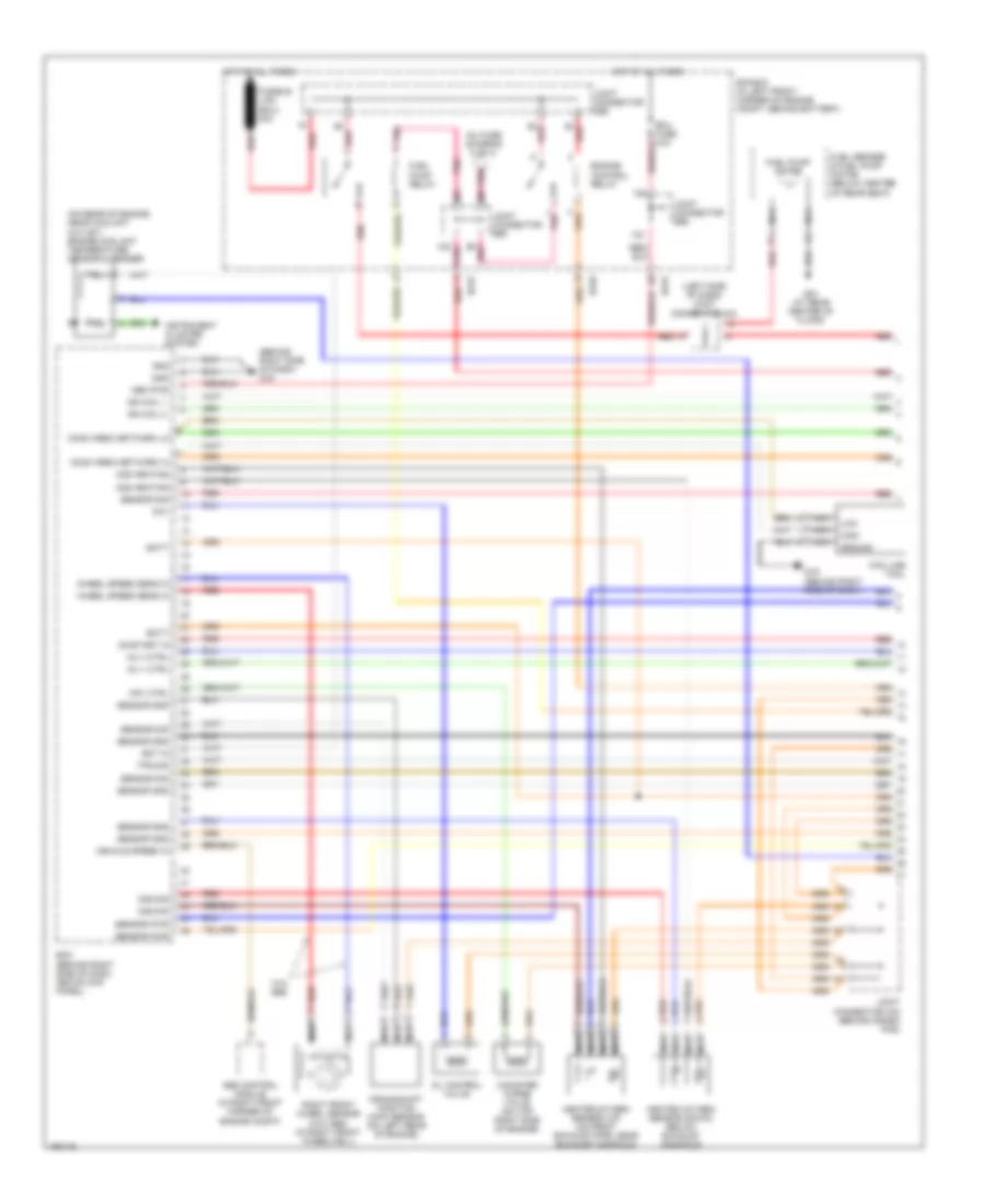
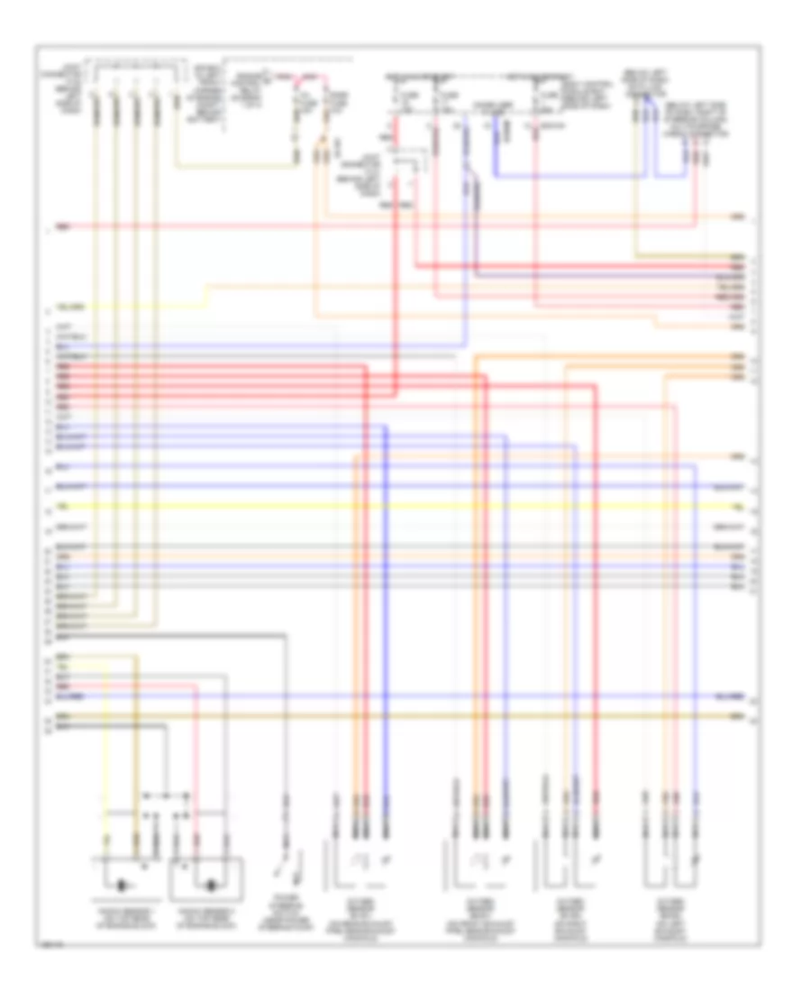
2.0L, Engine Performance Wiring Diagram (1 of 3) for Hyundai Tiburon 2004
 https://portal-diagnostov.com/license.html
Automotive Electricians Portal FZCO
Automotive Electricians Portal FZCO
https://portal-diagnostov.com/license.html
https://portal-diagnostov.com/license.html
Automotive Electricians Portal FZCO
Automotive Electricians Portal FZCO
List of elements for 2.0L, Engine Performance Wiring Diagram (1 of 3) for Hyundai Tiburon 2004:
- (behind right side of dash) g19
- (left side of dash) joint connector m34
- (on rear of engine, near coolant outlet) engine coolant temperature sensor & sender
- Abs control module (in right front corner of engine compt)
- Batt
- Can line tool
- Canister purge valve (on top right side of engine)
- Comm area network hi
- Comm area network lo
- Cpv ctrl
- Crankshaft position (ckp) sensor (on left rear of engine)
- E/r box (in left front corner of engine compt, behind battery)
- Ec01
- Ec02
- Ecm (behind right side of dash, above kick panel)
- Ect in
- Ecu fuse 10a
- Engine control relay
- Fuel pump motor
- Fuel pump relay
- Fuel sender & fuel pump motor (below center of rear seat)
- Fusible link (ecu) 30a
- G04 (at rear center of floor)
- G19 (behind right side of dash)
- Gnd
- Ground
- Heated oxygen sensor (down) (below exhaust manifold)
- Heated oxygen sensor (up) (on front exhaust pipe, near exhaust manifold)
- High
- Hot at all times
- Ign coil 1
- Ign coil 2
- Inj 1 ctrl
- Inj 4 ctrl
- Inj fuse (diagram 2 of 3)
- Instrument cluster system
- Joint connector c42 (behind crash pad)
- Joint connector e56
- Low
- Mem pwr
- Nca
- O2s heating
- O2s sig
- Ocv
- Oil control valve
- On/start in
- Pnk
- Red
- Right front wheel sensor (w/o abs) (in right front wheelwell)
- Sensor gnd
- Sensor pwr
- Sensor sig
- Sensor sns
- Tps sig
- Vehicle speed in
- W/o abs
- Wheel speed sens in
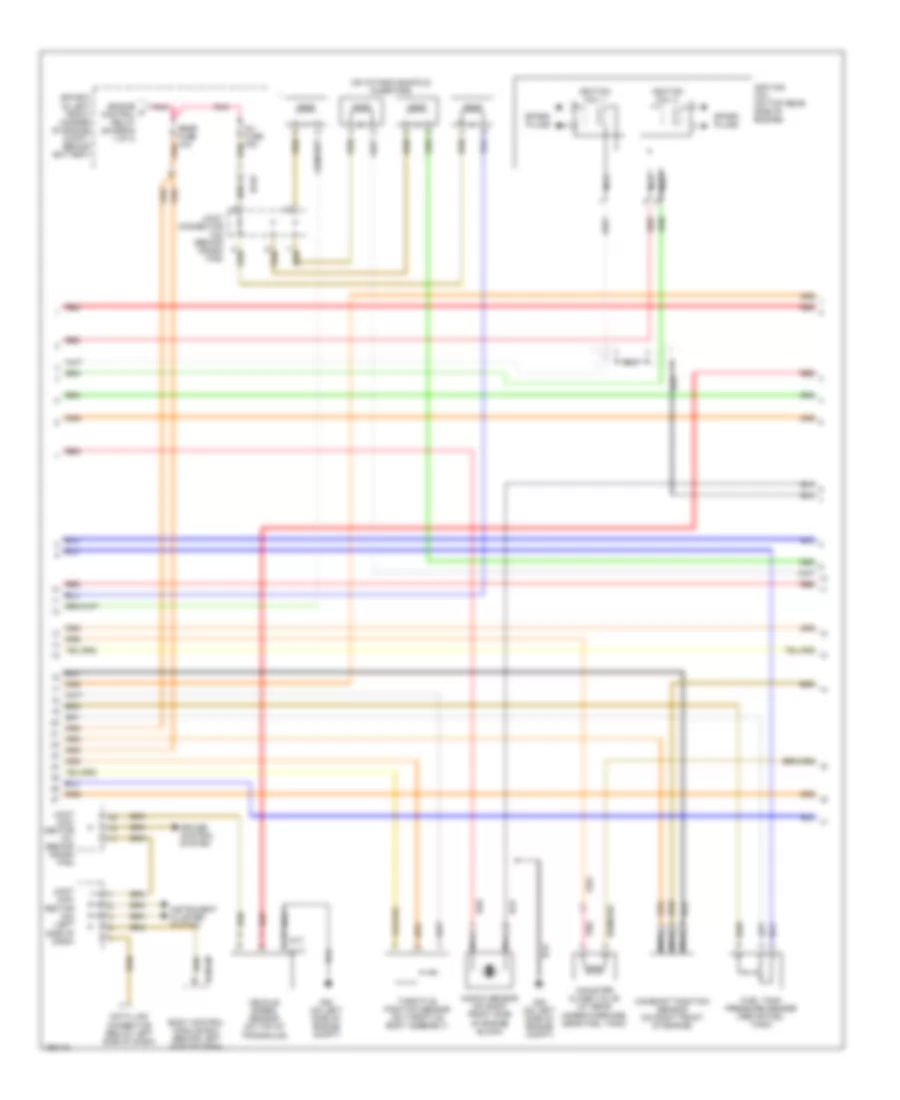
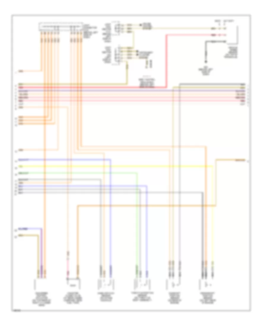
2.0L, Engine Performance Wiring Diagram (2 of 3) for Hyundai Tiburon 2004
 https://portal-diagnostov.com/license.html
Automotive Electricians Portal FZCO
Automotive Electricians Portal FZCO
https://portal-diagnostov.com/license.html
https://portal-diagnostov.com/license.html
Automotive Electricians Portal FZCO
Automotive Electricians Portal FZCOList of elements for 2.0L, Engine Performance Wiring Diagram (2 of 3) for Hyundai Tiburon 2004:
- (a/t)
- (m/t)
- (on intake manifold) injectors
- Bcm-jm
- Body control module box (behind left side of dash)
- Camshaft position sensor (on right front of engine)
- Canister close valve (at rear under-carriage, near fuel tank)
- Cruise control system
- Data link connector (below left side of dash)
- E/r box (in left front corner of engine compt, behind battery)
- Ec01
- Engine a control relay (diagram 1 of 3)
- Fuel tank pressure sensor (above fuel tank)
- G20 (on left side of engine compt)
- Ignition coil (on top rear side of engine)
- Ignition coil 1
- Ignition coil 2
- Inj fuse 15a
- Instrument cluster system
- Joint con- nector c41 (behind crash pad)
- Joint con- nector m34 (left side of dash)
- Joint connector c42 (behind crash pad)
- Knock sensor (on right front side of engine block)
- Nca
- Pnk
- Red
- Snsr fuse 10a
- Spark plugs
- Throttle position sensor (on throttle body assembly)
- Vehicle speed sensor (on top of transaxle)
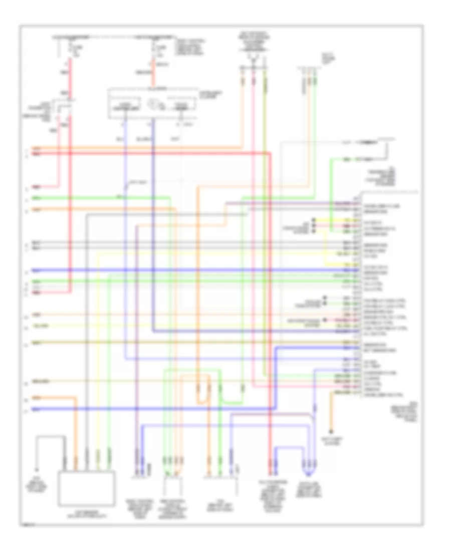
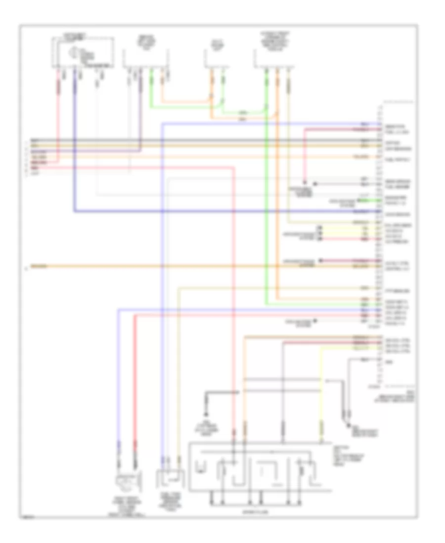
2.0L, Engine Performance Wiring Diagram (3 of 3) for Hyundai Tiburon 2004
 https://portal-diagnostov.com/license.html
Automotive Electricians Portal FZCO
Automotive Electricians Portal FZCO
https://portal-diagnostov.com/license.html
https://portal-diagnostov.com/license.html
Automotive Electricians Portal FZCO
Automotive Electricians Portal FZCOList of elements for 2.0L, Engine Performance Wiring Diagram (3 of 3) for Hyundai Tiburon 2004:
- (on top right rear of engine) idle speed control actuator
- A/c press sw in
- A/c relay ctrl
- A/c sig in
- A/c sw on in
- Abs control module (in right front corner of engine compt)
- Air conditioning system
- Anti-theft system
- Bcm-im
- Body control module box (behind left side of dash)
- C36-3
- Ccv ctrl
- Closing
- Cooling fans system
- Data link connector (below left side of dash)
- Diagnosis k-line
- Ecm (behind right side of dash, above kick panel)
- Ect sensor gnd
- Engine ctrl rly ctrl
- Engine rpm sig
- Fan relay (high) ctrl
- Fan relay (low) ctrl
- Fuel pump relay ctrl
- Fuse 10a
- G19 (behind right side of dash)
- Hot in on or start
- Iat sig
- Immobilizer ind ctrl
- Immobilizer w-line
- Inj 2 ctrl
- Inj 3 ctrl
- Inj sig
- Instrument cluster
- Joint connector c41 (behind crash pad)
- M10-1
- M10-2
- Maf sensor (on air intake duct)
- Maf sig
- Micro- controller
- Mil ind
- Mil ind ctrl
- Multi gauge unit
- Multipurpose check connector (below left side of dash, right of steering column)
- Nca
- Oil temp
- Oil temperature sensor (top right side of engine)
- Opening
- Pnk
- Red
- Sensor gnd
- Sensor sig
- Shield gnd
- Tacho- meter
- Tcm (behind left side of dash)
2.7L
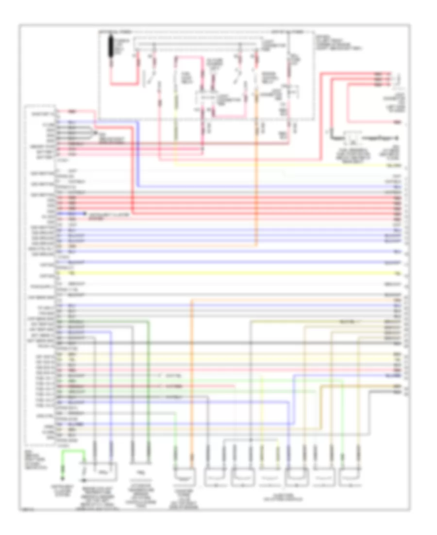
2.7L, Engine Performance Wiring Diagram (1 of 4) for Hyundai Tiburon 2004
 https://portal-diagnostov.com/license.html
Automotive Electricians Portal FZCO
Automotive Electricians Portal FZCO
https://portal-diagnostov.com/license.html
https://portal-diagnostov.com/license.html
Automotive Electricians Portal FZCO
Automotive Electricians Portal FZCOList of elements for 2.7L, Engine Performance Wiring Diagram (1 of 4) for Hyundai Tiburon 2004:
- (pins 11-16)
- (pins 2-6)
- (pins 2-7)
- (pins 27-28)
- (pins 39-41)
- (pins 43-45)
- (pins 49-52)
- (pins 8-12)
- 02s heating
- Air temp gnd
- Air temp sig
- Battery
- C133-1
- C133-2
- C133-3
- Canister purge valve (on top right side of engine)
- Ckp sens gnd
- Ckp sig
- Close
- Cps ctrl
- E/r box (in left front corner of engine compt, behind battery)
- Ec101
- Ec102
- Ecm (behind right side of dash, above kick)
- Ect sens gnd
- Ect sens in
- Ecu fuse 10a
- Eng ctrl rly
- Engine control relay
- Engine coolant temperature sensor & sender (on top left rear of cyl head, near coolant outlet)
- Fuel inj 1
- Fuel inj 2
- Fuel inj 3
- Fuel inj 4
- Fuel inj 5
- Fuel inj 6
- Fuel pump relay
- Fuel sender & fuel pump motor (below center of rear seat)
- Fusible link (ecu) 30a
- G04 (at rear center of floor)
- G22 (behind right side of dash)
- Gnd
- Hot at all times
- Inj fuse (diagram 2 of 4)
- Inj sig
- Injectors (on intake manifold)
- Instrument cluster system
- Intake air temperature sensor (on intake manifold surge tank)
- Joint connector e56
- Joint connector m34 (left side of dash)
- K-line
- Ks1 sig in
- Ks2 sig in
- Maf sens gnd
- Maf sig
- Memory pwr
- Nca
- O2s
- O2s ground
- O2s heating
- On/start in
- Open
- Pnk
- Ps sw in
- Red
- Tp input
- Tps gnd
2.7L, Engine Performance Wiring Diagram (2 of 4) for Hyundai Tiburon 2004
 https://portal-diagnostov.com/license.html
Automotive Electricians Portal FZCO
Automotive Electricians Portal FZCO
https://portal-diagnostov.com/license.html
https://portal-diagnostov.com/license.html
Automotive Electricians Portal FZCO
Automotive Electricians Portal FZCOList of elements for 2.7L, Engine Performance Wiring Diagram (2 of 4) for Hyundai Tiburon 2004:
- (below left side of dash) data link connector
- (below left side of dash, right of steering column) multipurpose check connector
- Bcm-im
- Bcm-km
- Body control module box (behind left side of dash)
- E/r box (in left front corner of engine compt, behind battery)
- Ec101
- Engine a control relay (diagram 1 of 4)
- Fuse 10a
- Fuse 20a
- Hot in on or start
- Immobilizer w line
- Inj fuse 15a
- Joint connector c141 (behind left side of dash)
- Joint connector c142 (behind left side of dash)
- Knock sensor 1 (on top rear of engine block)
- Knock sensor 2 (on top rear of engine block)
- Nca
- Oxygen sensor (b1/s1) (on rear exhaust pipe, near exhaust manifold)
- Oxygen sensor (b1/s2) (on right exhaust manifold)
- Oxygen sensor (b2/s1) (on front exhaust pipe, near exhaust manifold)
- Oxygen sensor (b2/s2) (on left exhaust manifold)
- Pnk
- Power steering switch (near power steering pump)
- Red
- Snsr fuse 10a
2.7L, Engine Performance Wiring Diagram (3 of 4) for Hyundai Tiburon 2004
 https://portal-diagnostov.com/license.html
Automotive Electricians Portal FZCO
Automotive Electricians Portal FZCO
https://portal-diagnostov.com/license.html
https://portal-diagnostov.com/license.html
Automotive Electricians Portal FZCO
Automotive Electricians Portal FZCOList of elements for 2.7L, Engine Performance Wiring Diagram (3 of 4) for Hyundai Tiburon 2004:
- (a/t, 6m/t) (5m/t)
- Bcm-jm
- Body control module box (behind left side of dash)
- Camshaft position sensor (on rear of engine)
- Canister close valve (at rear under- carriage, near fuel tank)
- Crankshaft position sensor (on left rear of engine)
- Cruise control system
- G23 (behind left side of dash)
- Idle speed control actuator (on top rear of right cylinder head)
- Instrument cluster system
- Joint con- nector c141 (behind left side of dash)
- Joint con- nector m34 (left side of dash)
- Joint connector c142 (behind left side of dash)
- Mass air flow sensor (on intake manifold)
- Nca
- Pnk
- Red
- Throttle position sensor (on throttle body assembly)
- Vehicle speed sensor (on top of transaxle)
2.7L, Engine Performance Wiring Diagram (4 of 4) for Hyundai Tiburon 2004
 https://portal-diagnostov.com/license.html
Automotive Electricians Portal FZCO
Automotive Electricians Portal FZCO
https://portal-diagnostov.com/license.html
https://portal-diagnostov.com/license.html
Automotive Electricians Portal FZCO
Automotive Electricians Portal FZCOList of elements for 2.7L, Engine Performance Wiring Diagram (4 of 4) for Hyundai Tiburon 2004:
- (behind left side of dash) tcm
- (in right front corner of engine compt) abs control module
- (on top rear of left cylinder head)
- A/c on in
- A/c pres sw
- A/c rly ctrl
- A/c sig in
- Air conditioning system
- C133-4
- C133-5
- C136-1
- C136-3
- Chck eng ind
- Cmp sens gnd
- Cmp sig
- Comm net hi
- Comm net lo
- Control vlv
- Cooling fans system
- Ecm (behind right side of dash, above kick)
- Engine rpm
- Fan rly hi
- Fan rly lo
- Ftp sens sig
- Fuel lvl sig
- Fuel pmp rly
- Fuel sender
- Fuel tank pressure sensor (above fuel tank)
- G22 (behind right side of dash)
- G24 (top rear of cylinder head)
- Gnd
- Ign coil ctrl
- Ignition coil
- Instrument cluster
- Instrument cluster system
- M10-1
- M10-2
- Mil (check engine ind)
- Multi gauge unit
- Nca
- Red
- Right front wheel sensor (w/o abs) (in right front wheelwell)
- Sens ground
- Sens pwr
- Spark plugs
- Tachometer
- Whl spd in
- Whl spd sens

 Čeština
 Dansk
Dansk Deutsch
 Ελληνικά
 English
 English
 Español
 Suomi
Suomi Français
 Français
 עברית
עברית Hrvatski
 Magyar
 Italiano
 日本語
日本語 한국어
한국어 Nederlands
 Polski
 Português
 Português
 Română
 Русский
 Slovenčina
 Slovenščina
 Svenska
 中文 (中国)
