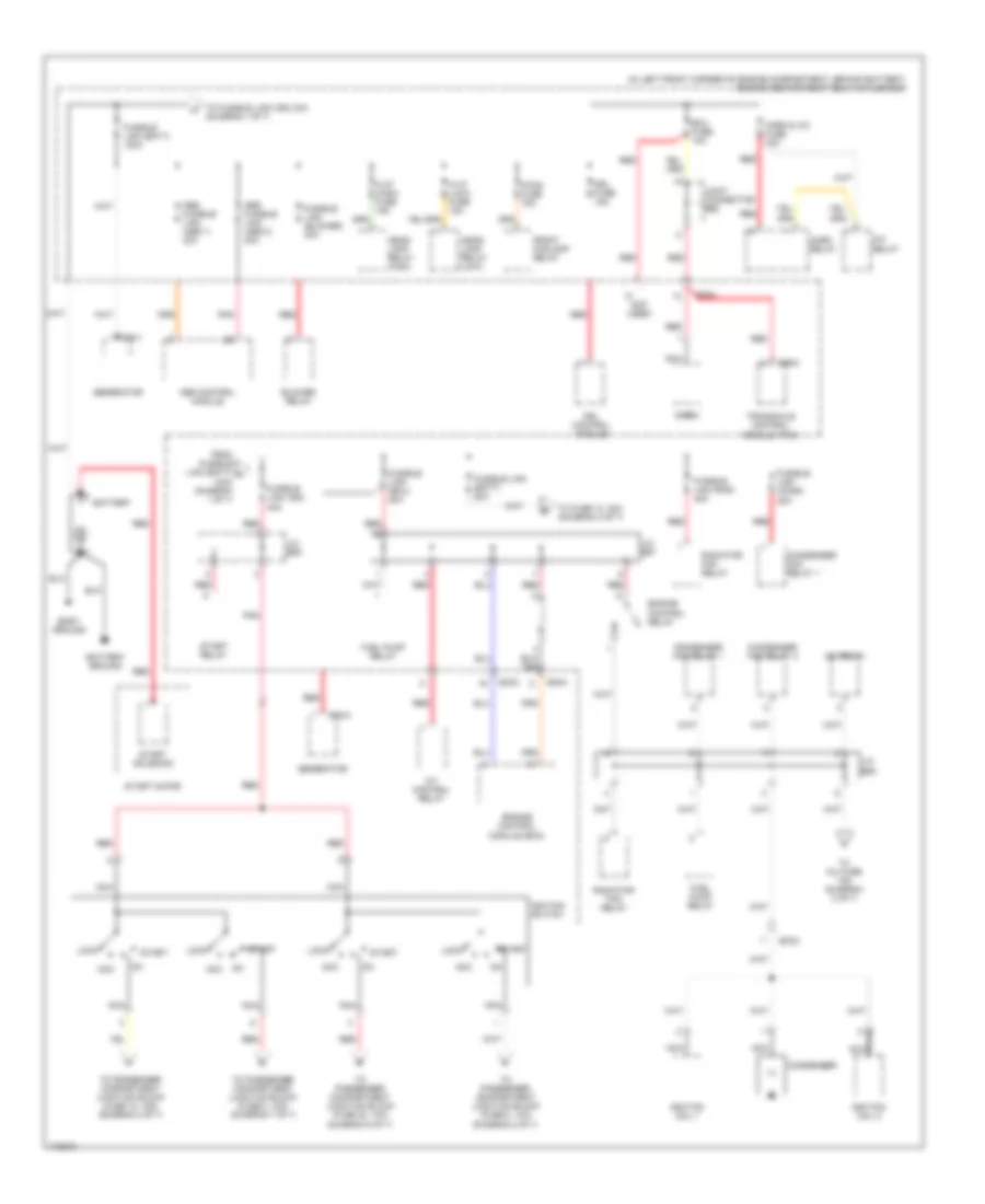
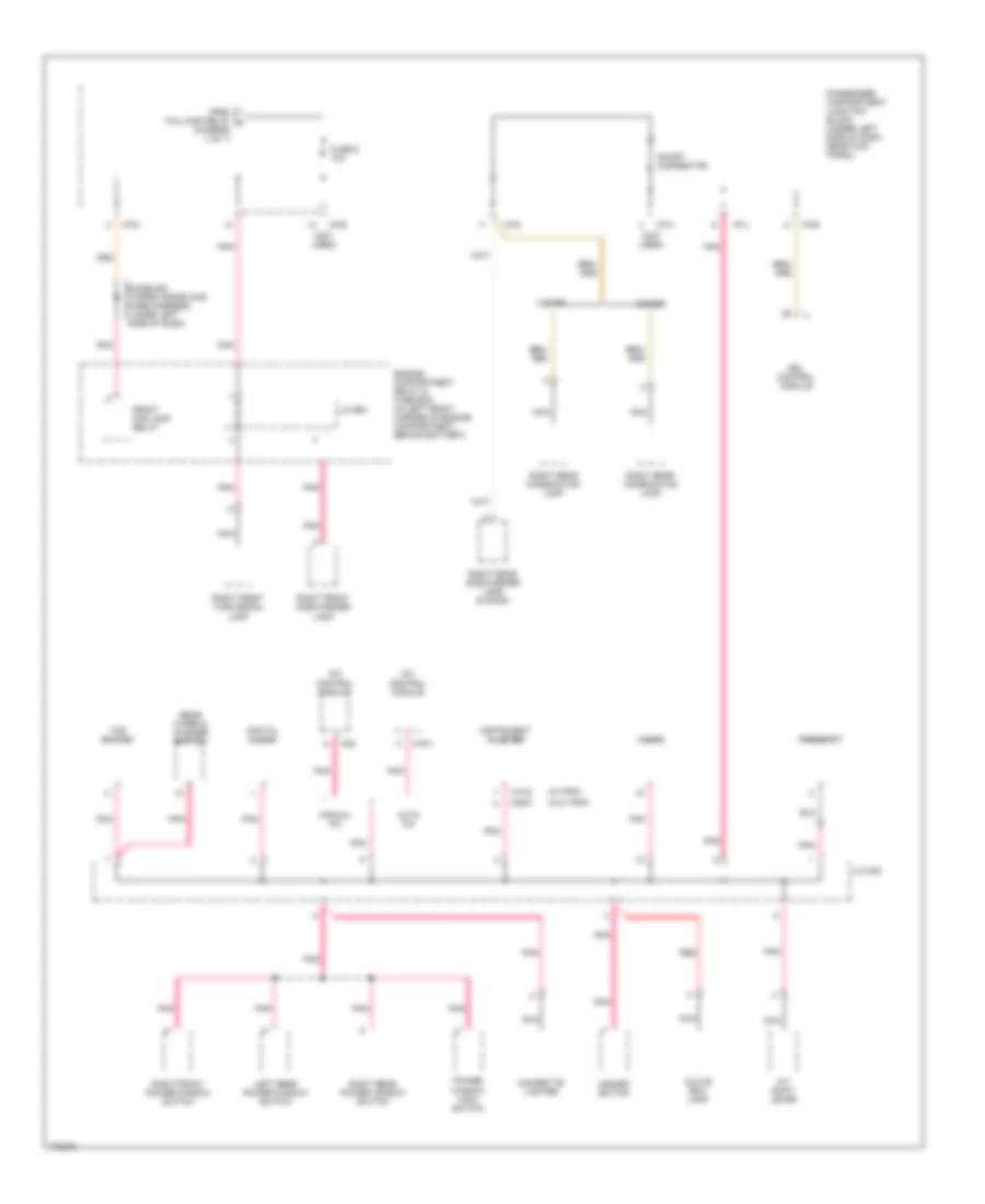
POWER DISTRIBUTION
Power Distribution Wiring Diagram (1 of 7) for Hyundai Elantra GT 2003
 https://portal-diagnostov.com/license.html
Automotive Electricians Portal FZCO
Automotive Electricians Portal FZCO
https://portal-diagnostov.com/license.html
https://portal-diagnostov.com/license.html
Automotive Electricians Portal FZCO
Automotive Electricians Portal FZCO
List of elements for Power Distribution Wiring Diagram (1 of 7) for Hyundai Elantra GT 2003:
- (in left front corner of engine compartment, behind battery) engine compartment relay & fuse box
- (not used)
- A/c relay
- A/t control relay
- Abs control module
- Abs fusible link (abs 1) 30a
- Abs fusible link (abs 2) 30a
- Acc
- Battery
- Battery ground
- Blower relay
- Body ground
- C86-2
- Condenser
- Condenser fan relay 1
- Condenser fan relay 2
- Drl control module
- Drl fuse 15a
- E20-1
- E20-2
- Ec03
- Ec04
- Ecu fuse 10a
- Engine control module (ecm)
- Engine control relay
- F/fog fuse 15a
- From fusible link (batt) a 100a (diagram 1 of 7)
- Front foglamp relay
- Fuel pump relay
- Fusible link (batt) 100a
- Fusible link (batt) 50a
- Fusible link (blower) 30a
- Fusible link (cond) 20a
- Fusible link (ecu) 20a
- Fusible link (ign) 40a
- Fusible link (rad) 20a
- Generator
- H/lp (high) fuse 15a
- H/lp (low) fuse 15a
- Head- lamp relay (high)
- Head- lamp relay (low)
- Horn & a/c fuse 15a
- Horn relay
- Ignition coil 1
- Ignition coil 2
- Ignition switch
- J/c e55
- J/c e57
- J/c e58
- Joint connector e62
- Lock
- Nca
- Pnk
- Radiator fan relay
- Red
- Siren
- Start
- Start motor
- Start relay
- Start solenoid
- To fuse 13, 30a (diagram 3 of 7)
- To fusible link (ign) 40a (diagram 1 0f 7)
- To inj fuse 15a (diagram 2 of 7)
- To passenger compartment junction block (fuse 18, 15a) (diagram 2 of 7)
- To passenger compartment junction block (fuse 2, 10a) (diagram 7 of 7)
- To passenger compartment junction block (fuse 20, 10a) (diagram 6 of 7)
- To passenger compartment junction block (fuse 8, 10a) (diagram 2 of 7)
- Transaxle control module (tcm)
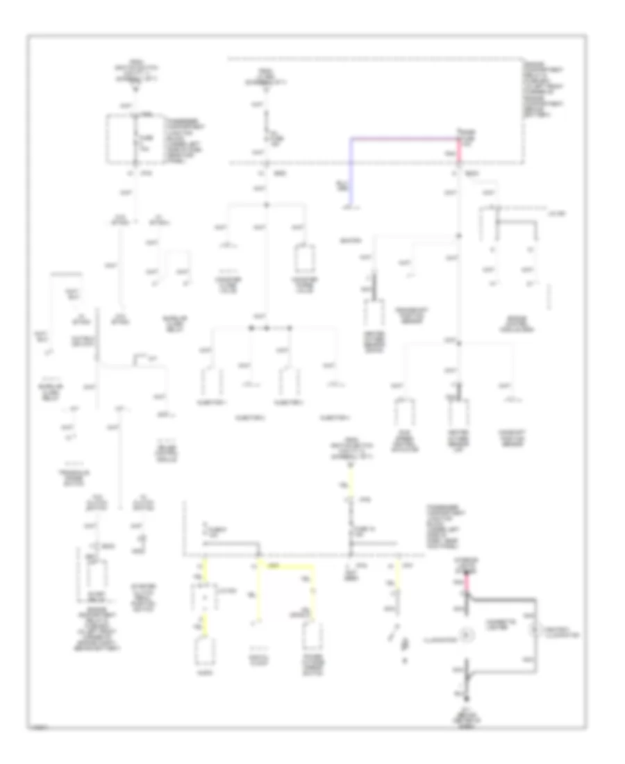
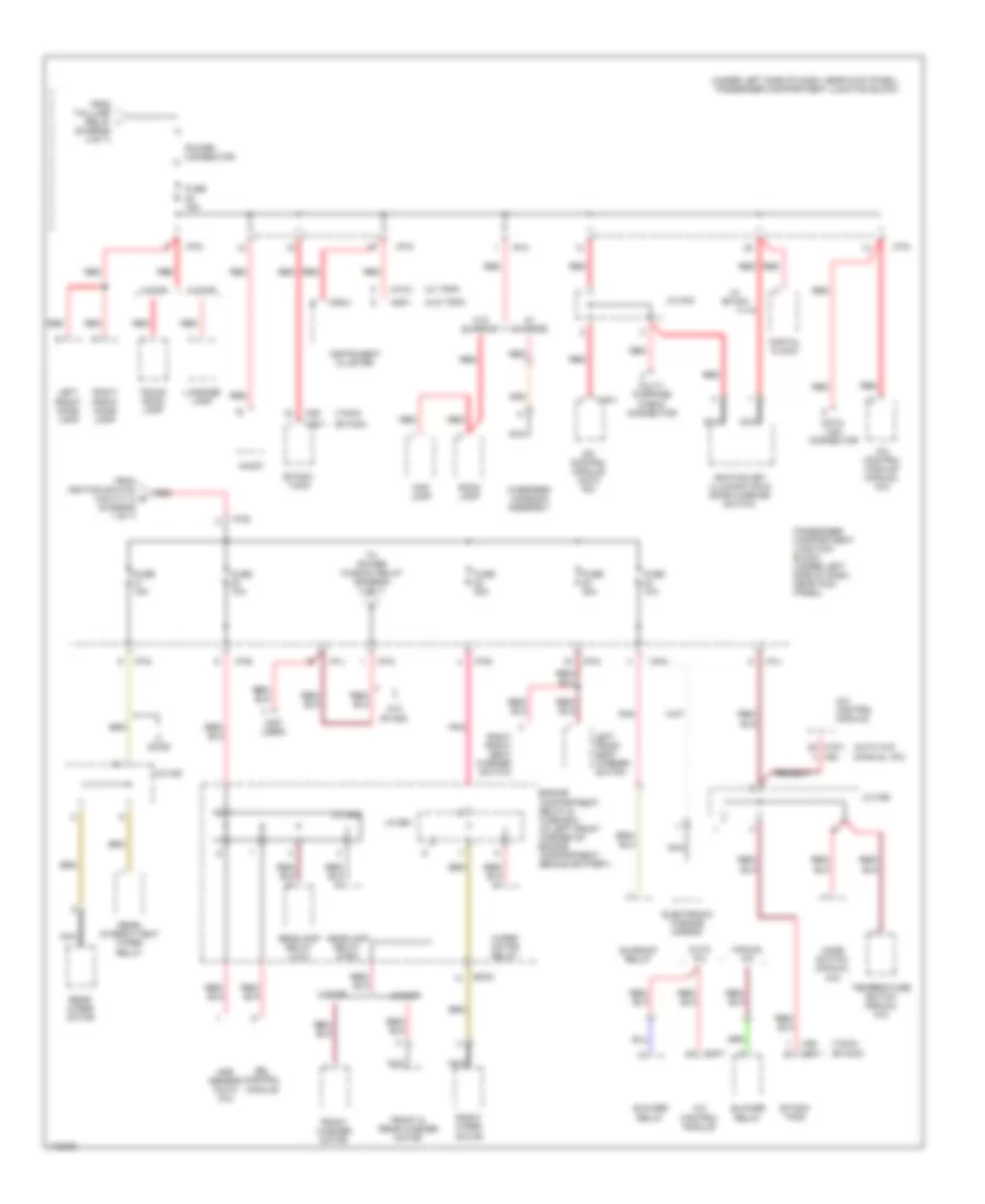
Power Distribution Wiring Diagram (2 of 7) for Hyundai Elantra GT 2003
 https://portal-diagnostov.com/license.html
Automotive Electricians Portal FZCO
Automotive Electricians Portal FZCO
https://portal-diagnostov.com/license.html
https://portal-diagnostov.com/license.html
Automotive Electricians Portal FZCO
Automotive Electricians Portal FZCOList of elements for Power Distribution Wiring Diagram (2 of 7) for Hyundai Elantra GT 2003:
- (not used)
- A/t
- Ashtray illumination
- Audio
- Burglar alarm relay
- Camshaft position sensor
- Canister close valve
- Canister purge valve
- Cigarette lighter
- Crankshaft position sensor
- Cruise control module
- Digital clock
- Ec03
- Engine compartment relay & fuse box (in left front corner of engine compartment, behind battery)
- Engine compartment relay & fuse box (in left front corner of engine compt, behind battery)
- Engine control module (ecm)
- From ignition switch (cavity 1) (diagram 1 of 7)
- From ignition switch (cavity 4) (diagram 1 of 7)
- From j/c e58 (diagram 1 of 7)
- Fuse 10a
- Fuse 18 15a
- Fuse 9 10a
- G11 (behind center of dash)
- Heated oxygen sensor (down)
- Heated oxygen sensor (up)
- I/p-d
- I/p-e
- I/p-f
- I/p-g
- Idle speed control actuator
- Illumination
- Inj fuse 15a
- Injector 1
- Injector 2
- Injector 3
- Injector 4
- Interior lights system
- J/c c91
- J/c m33
- M/t
- Nca
- Passenger compartment junction block (under left side of dash, near kick panel)
- Pnk
- Power outside mirror switch
- Smatra
- Snsr fuse 1oa
- Start relay
- Starter clutch pedal position switch
- Transaxle range switch
- W/ clutch switch
- W/ etacm
- W/o clutch switch
- W/o etacm
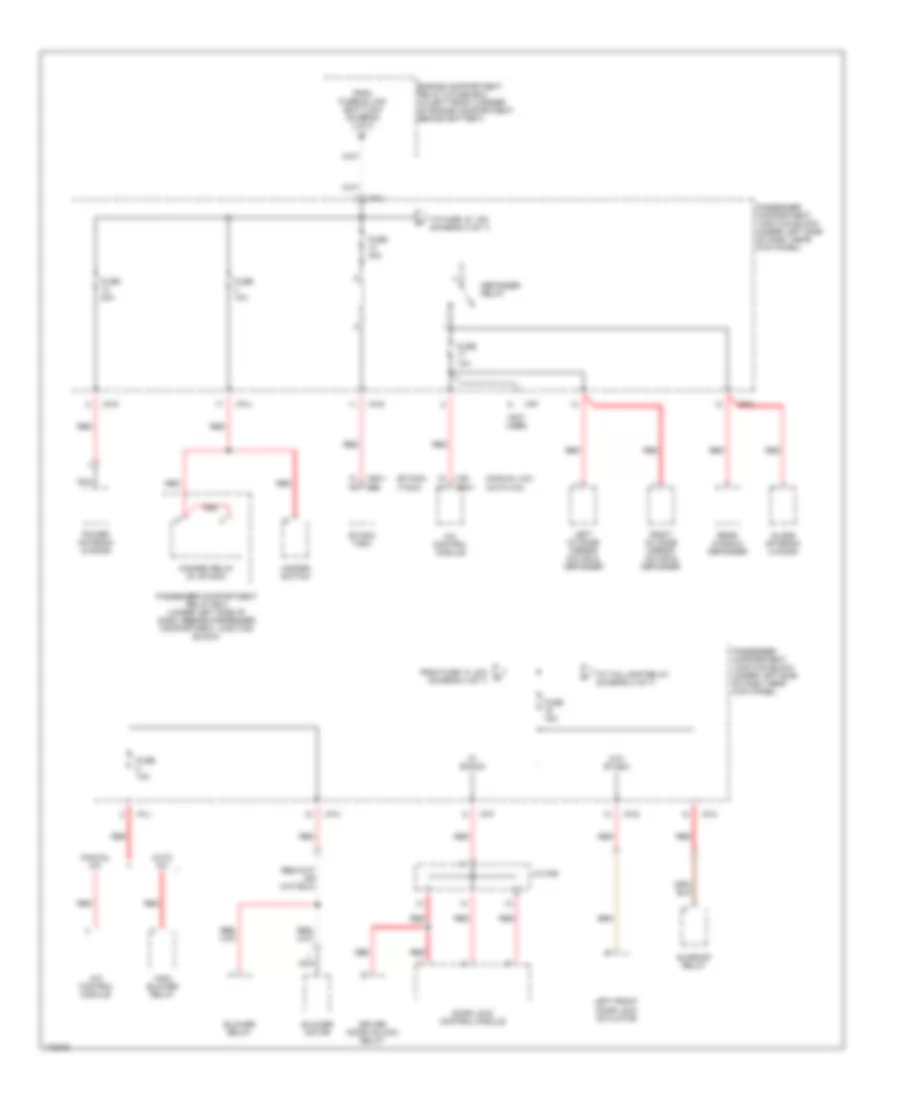
Power Distribution Wiring Diagram (3 of 7) for Hyundai Elantra GT 2003
 https://portal-diagnostov.com/license.html
Automotive Electricians Portal FZCO
Automotive Electricians Portal FZCO
https://portal-diagnostov.com/license.html
https://portal-diagnostov.com/license.html
Automotive Electricians Portal FZCO
Automotive Electricians Portal FZCOList of elements for Power Distribution Wiring Diagram (3 of 7) for Hyundai Elantra GT 2003:
- (etacm) (tacm)
- (manual a/c) (auto a/c)
- (not used)
- A/c control module
- Auto a/c
- Blower motor
- Blower relay
- Defogger relay
- Door lock control module
- Driver door unlock relay
- Engine compartment relay & fuse box (in left front corner of engine compartment, behind battery)
- Etacm/ tacm
- From fuse 13, 30a (diagram 3 of 7)
- From fusible link (batt) 50a (diagram 1 of 7)
- Fuse 10a
- Fuse 15a
- Fuse 20a
- Fuse 30a
- Glass antenna (4 door)
- Hazard relay (w/ etacm)
- Hazard switch
- High blower relay
- I/p-a
- I/p-c
- I/p-d
- I/p-f
- I/p-g
- I/p-h
- I/p-j
- J/c m36
- Left front door lock actuator
- Left outside mirror motor & defogger
- M20 m19-1
- M25-1 m26
- Manual a/c
- Nca
- Passenger compartment junction block (under left side of dash, near kick panel)
- Passenger compartment relay box (under left side of dash, beside passenger compartment junction block)
- Power antenna (5 door)
- Rear window defogger
- Red
- Right outside mirror motor & defogger
- Sunroof relay
- To fuse 15, 15a (diagram 3 of 7)
- To taillamp relay (diagram 4 of 7)
- W/ etacm
- W/o etacm
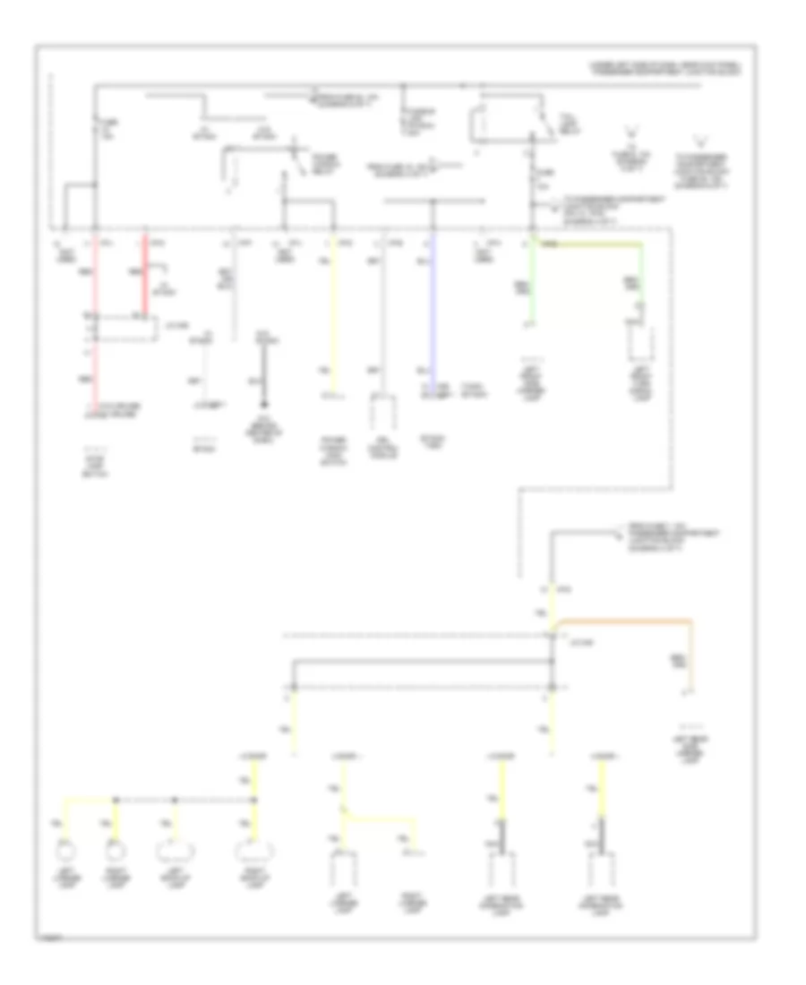
Power Distribution Wiring Diagram (4 of 7) for Hyundai Elantra GT 2003
 https://portal-diagnostov.com/license.html
Automotive Electricians Portal FZCO
Automotive Electricians Portal FZCO
https://portal-diagnostov.com/license.html
https://portal-diagnostov.com/license.html
Automotive Electricians Portal FZCO
Automotive Electricians Portal FZCOList of elements for Power Distribution Wiring Diagram (4 of 7) for Hyundai Elantra GT 2003:
- (etacm)
- (not used)
- (tacm)
- (under left side of dash, near kick panel) passenger compartment junction block
- (w/ cruise)
- (w/o cruise)
- 4 door
- 5 door
- Drl control module
- Etacm
- Etacm/ tacm
- From fuse 15, 15a f (diagram 3 of 7)
- From fuse 20, 10a (diagram 6 of 7)
- From fuse 7, 10a passenger compartment junction block (diagram 4 of 7)
- Fuse 10a
- Fuse 15a
- Fusible link (p/wdw) 30a
- G12 (behind center of dash)
- I/p-b
- I/p-d
- I/p-f
- I/p-g
- I/p-h
- I/p-j
- J/c m36
- J/c m45
- Left back-up lamp
- Left front side marker lamp
- Left front turn signal lamp
- Left license lamp
- Left rear combination lamp
- Left rear side marker lamp
- M25-1
- M26 m25-1
- Nca
- Power window main switch
- Power window relay
- Red
- Right back-up lamp
- Right license lamp
- Stop lamp switch
- Tail- lamp relay
- To fuse 6, 10a (diagram 5 of 7)
- To passenger compartment junction block (pin 10, i/p-d) (diagram 4 of 7)
- To passenger compartment junction block fuse 25, 15a (diagram 6 of 7)
- W/ etacm
- W/o etacm
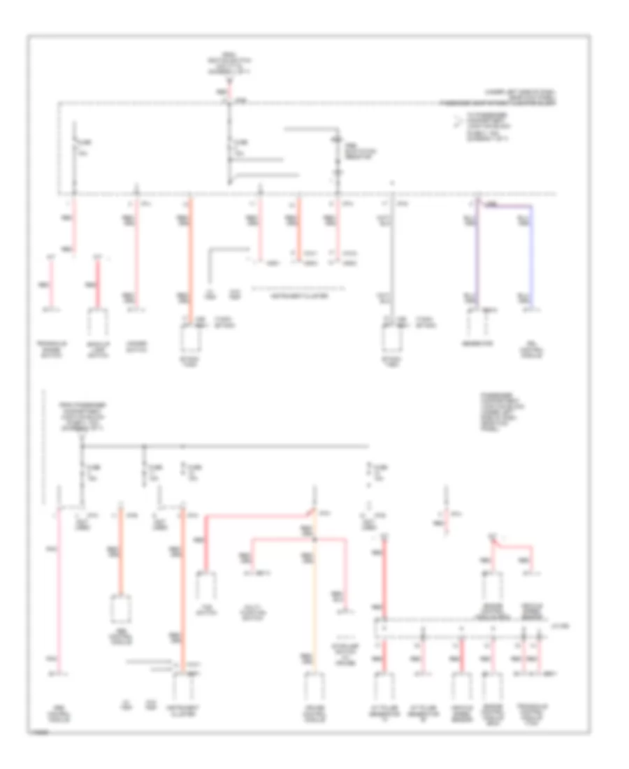
Power Distribution Wiring Diagram (5 of 7) for Hyundai Elantra GT 2003
 https://portal-diagnostov.com/license.html
Automotive Electricians Portal FZCO
Automotive Electricians Portal FZCO
https://portal-diagnostov.com/license.html
https://portal-diagnostov.com/license.html
Automotive Electricians Portal FZCO
Automotive Electricians Portal FZCOList of elements for Power Distribution Wiring Diagram (5 of 7) for Hyundai Elantra GT 2003:
- (not used)
- (w/o trip)
- (w/trip)
- 4 door
- 5 door
- A/c control module
- A/t shift lever
- Audio
- Auto a/c
- Cigarette lighter
- Digital clock
- Diode z02 (taped inside main wire harness, lower left side of dash)
- Drl control module
- Engine compartment relay & fuse box (in left front corner of engine compartment, behind battery)
- From taillamp relay h (diagram 4 of 7)
- Front fog lamp relay
- Fuse 6 10a
- Glove box lamp
- Hazard switch
- I/p-b
- I/p-c
- I/p-d
- I/p-g
- I/p-j
- Instrument cluster
- J/c e61
- J/c m08
- Left rear power window switch
- M09-3
- M10-2
- M19-1
- M20
- Manual a/c
- Nca
- Passenger compartment junction block (under left side of dash, near kick panel)
- Pnk
- Power window main switch
- Rear wiper & washer switch
- Red
- Rheostat
- Right front power window switch
- Right front side marker lamp
- Right front turn signal lamp
- Right rear combination lamp
- Right rear power window switch
- Right rear side marker lamp (5 door)
- Short connector
- Tcs switch
Power Distribution Wiring Diagram (6 of 7) for Hyundai Elantra GT 2003
 https://portal-diagnostov.com/license.html
Automotive Electricians Portal FZCO
Automotive Electricians Portal FZCO
https://portal-diagnostov.com/license.html
https://portal-diagnostov.com/license.html
Automotive Electricians Portal FZCO
Automotive Electricians Portal FZCOList of elements for Power Distribution Wiring Diagram (6 of 7) for Hyundai Elantra GT 2003:
- (auto a/c)
- (diagram 1 of 7)
- (diagram 4 of 7)
- (etacm)
- (manual a/c)
- (not used)
- (tacm)
- (under left side of dash, near kick panel) passenger compartment junction block
- (w/ trip)
- (w/o trip)
- 4 door
- 5 door
- A/c control module
- A/c control module (auto a/c)
- A/c control module (manual a/c)
- Aqs sensor (auto a/c)
- Audio
- Auto a/c
- Blower relay
- Data link connector
- Digital clock
- Door
- Drl control module
- Ec03
- Electronic chrome mirror
- Engine compartment relay & fuse box (in left front corner of engine compartment, behind battery)
- Etacm/ tacm
- From ignition switch (cavity 3) e
- From taillamp relay i
- Front & rear washer motor
- Front washer motor
- Front wiper motor
- Fuse 10a
- Fuse 15a
- Fuse 20a
- Headlamp relay (high)
- Headlamp relay (low)
- I/p-b
- I/p-c
- I/p-d
- I/p-e
- I/p-g
- I/p-j
- Ignition key illumination & door warning switch
- Instrument cluster
- J/c e56
- J/c e61
- J/c m33
- J/c m36
- J/c m45
- Left front door lamp
- Left front seat warmer switch
- Luggage lamp
- M09-1
- M09-3
- M10-2
- M19-1
- M20
- M25-1
- M26
- Manual a/c
- Map lamp
- Mode switch (manual a/c)
- Multi- purpose check connector
- Nca
- Overhead console assembly
- Passenger compartment junction block (under left side of dash, near kick panel)
- Pnk
- Power connector
- Rear intermittent wiper relay
- Rear wiper motor
- Red
- Right front door lamp
- Right front seat warmer switch
- Room lamp
- Sunroof relay
- Temperature switch (manual a/c)
- To power window relay (diagram 4 of 7)
- Trunk room lamp
- W/ etacm
- W/ sunroof
- W/o etacm
- W/o sunroof
- Wiper motor relay
Power Distribution Wiring Diagram (7 of 7) for Hyundai Elantra GT 2003
 https://portal-diagnostov.com/license.html
Automotive Electricians Portal FZCO
Automotive Electricians Portal FZCO
https://portal-diagnostov.com/license.html
https://portal-diagnostov.com/license.html
Automotive Electricians Portal FZCO
Automotive Electricians Portal FZCOList of elements for Power Distribution Wiring Diagram (7 of 7) for Hyundai Elantra GT 2003:
- (etacm)
- (fuse 3, 15a) (diagram 7 of 7)
- (not used)
- (tacm)
- (under left side of dash, near kick panel) passenger compartment junction block
- A/t
- A/t pulse generator "a"
- A/t pulse generator "b"
- Abs control module
- Back-up lamp switch
- C86-1
- Cruise control module
- Drl control module
- E20-2
- Engine control module (ecm)
- Etacm/ tacm
- From ignition switch (cavity 6) (diagram 1 of 7)
- From passenger compartment junction block (fuse 2, 10a) (diagram 7 of 7)
- Fuse 10a
- Fuse 15a
- Generator
- Hazard switch
- I/p-b
- I/p-e
- I/p-g
- I/p-h
- I/p-j
- I/p-k
- Instrument cluster
- J/c c92
- M/t
- M01-3
- M09-1
- M09-2
- M09-3
- M10-1
- M10-2
- M25-1
- M26
- Multi- function switch
- Passenger compartment junction block (under left side of dash, near kick panel)
- Pnk
- Pre- excitation resistor
- Red
- Srs control module
- Stoplamp switch (w/ cruise)
- Tcs switch
- To passenger compartment junction block
- Transaxle control module (tcm)
- Transaxle range switch
- Vehicle speed sensor
- W/ trip
- W/o trip

 Čeština
 Dansk
Dansk Deutsch
 Ελληνικά
 English
 English
 Español
 Suomi
Suomi Français
 Français
 עברית
עברית Hrvatski
 Magyar
 Italiano
 日本語
日本語 한국어
한국어 Nederlands
 Polski
 Português
 Português
 Română
 Русский
 Slovenčina
 Slovenščina
 Svenska
 中文 (中国)
