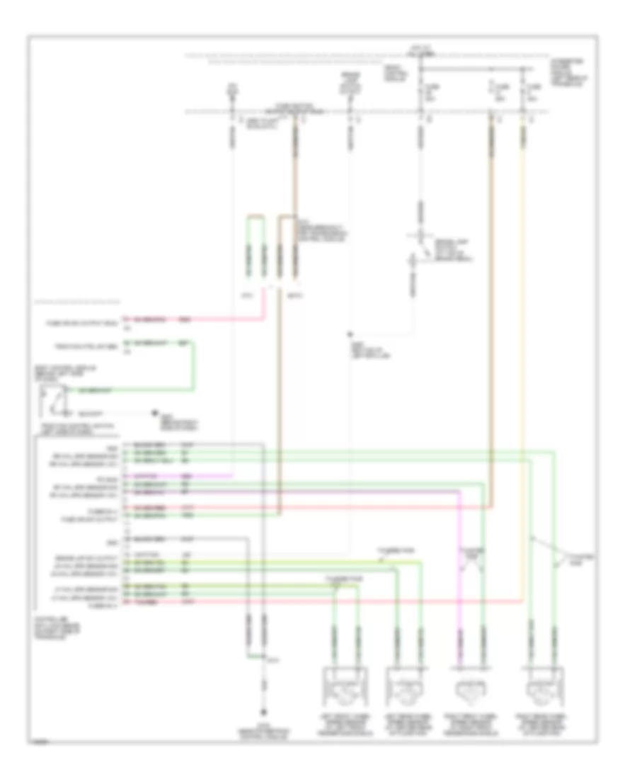
ANTI-LOCK BRAKES
Anti-lock Brakes Wiring Diagram for Chrysler Town & Country LX 2004
 https://portal-diagnostov.com/license.html
Automotive Electricians Portal FZCO
Automotive Electricians Portal FZCO
https://portal-diagnostov.com/license.html
https://portal-diagnostov.com/license.html
Automotive Electricians Portal FZCO
Automotive Electricians Portal FZCO
List of elements for Anti-lock Brakes Wiring Diagram for Chrysler Town & Country LX 2004:
- 20a
- 25a
- 40a
- A107
- A111
- Assy plant evac & fill
- B27
- Body control module (behind left side of dash)
- Brake lamp switch (at top of brake pedal)
- Brake lamp switch output
- Brake lmp sw output
- Controller anti-lock brake (on right side of transaxle)
- D25
- Eatx
- F500
- Front control module
- Fuse
- Fuse ign sw output
- Fuse ign sw output (run)
- Fuse ignition switch output (run)
- Fused b (+)
- G100 (near powertrain control module)
- G200 (behind right side of dash)
- Gnd
- Hot at all times
- Integrated power module (left rear of transaxle)
- L50
- Left front wheel speed sensor (at left front fender side shield)
- Left rear wheel speed sensor (at center rear of floor pan)
- Lf whl spd sensor (12v)
- Lf whl spd sensor sig
- Lr whl spd sensor (12v)
- Lr whl spd sensor sig
- Mtx
- Pci bus
- Rf whl spd sensor (12v)
- Rf whl spd sensor sig
- Right front wheel speed sensor (at right front fender side shield)
- Right rear wheel speed sensor (at center rear of floor pan)
- Rr whl spd sensor (12v)
- Rr whl spd sensor sig
- S131 (near breakout for transmission control module)
- S141
- S367 (bottom of left"b"pillar)
- Tan/red
- Traction control switch (left side of dash)
- Traction ctrl sw sen
- Twisted pair
- Z107
- Z127
 Čeština
 Dansk
Dansk Deutsch
 Ελληνικά
 English
 English
 Español
 Suomi
Suomi Français
 Français
 עברית
עברית Hrvatski
 Magyar
 Italiano
 日本語
日本語 한국어
한국어 Nederlands
 Polski
 Português
 Português
 Română
 Русский
 Slovenčina
 Slovenščina
 Svenska
 中文 (中国)
 Türkçe
