СИСТЕМА УПРАВЛЕНИЯ ДВИГАТЕЛЯ
4.6L
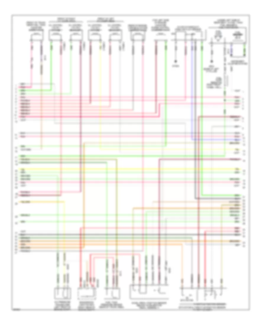
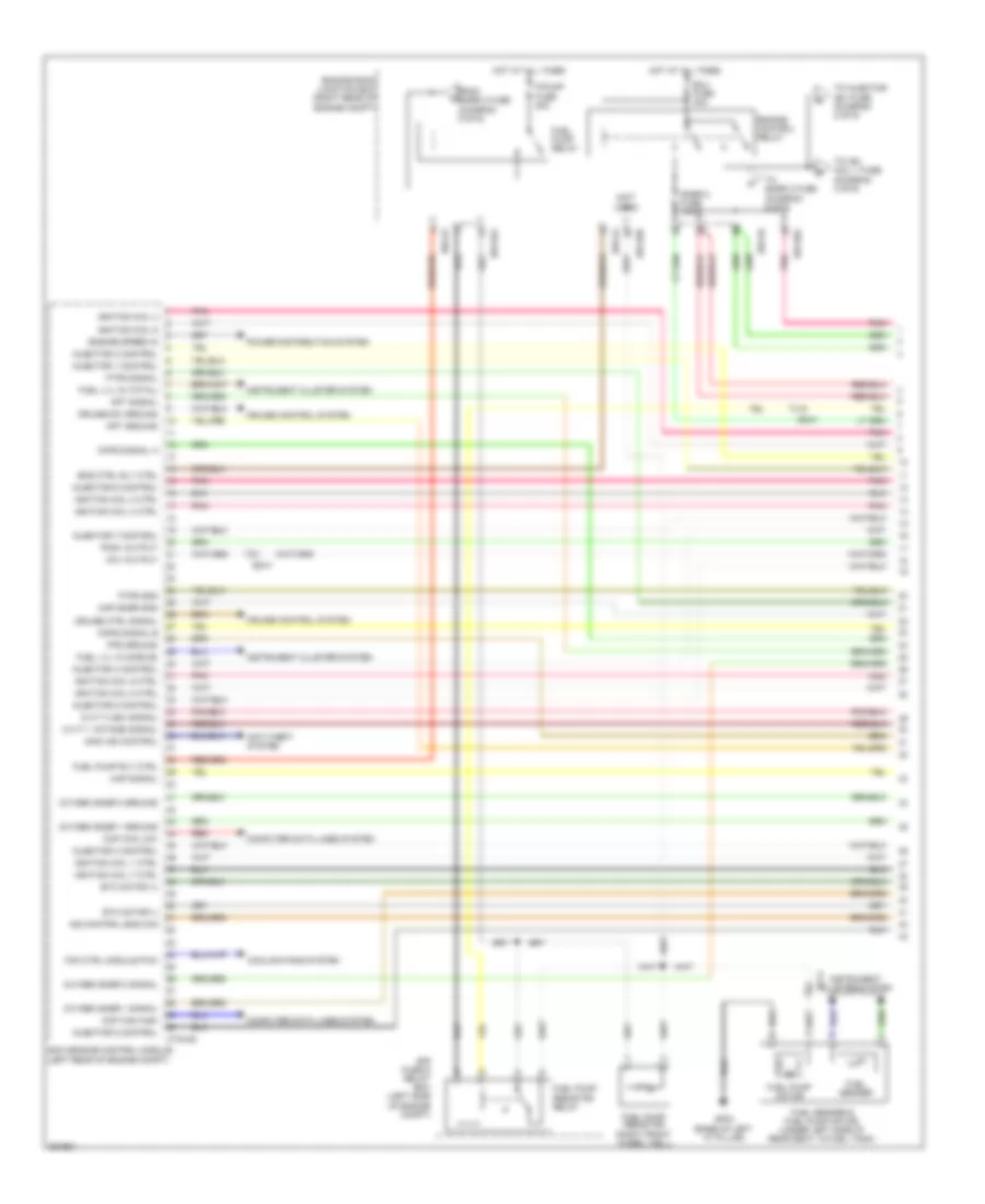
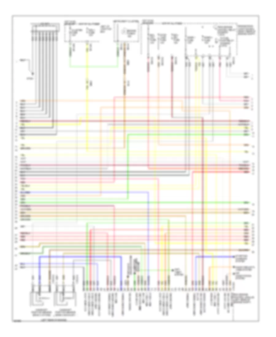
4.6L, Электросхема системы управления двигателя (1 из 5) для Hyundai Equus Ultimate 2012
 https://portal-diagnostov.com/license.html
Automotive Electricians Portal FZCO
Automotive Electricians Portal FZCO
https://portal-diagnostov.com/license.html
https://portal-diagnostov.com/license.html
Automotive Electricians Portal FZCO
Automotive Electricians Portal FZCO
4.6L, Электросхема системы управления двигателя (1 из 5) для Hyundai Equus Ultimate 2012 - Список элементов:
- Ccp can high
- Ccp can low
- Ccv output
- Computer data lines system
- Cooling fans system
- Cruise control system
- Cruise ctrl ground
- Cruise ctrl signal
- Ctg-a
- Ctg24-1
- Ctg24-2
- Ctg24-3
- Ctg24-4
- Ctg24-5
- Ctg24-6
- Ctg24-7
- Ctg24-8
- Cvvt 1 signal
- Cvvt 2 signal
- E/r-ca
- E/r-cb
- E/r-e1a
- E/r-e2a
- Ec01
- Ecm (engine control module) (left rear of engine compt)
- Ecu fuse 30a
- Em31
- Eng ctrl rly ctrl
- Eng snsr-2 fuse 10a
- Eng snsr-3 fuse 15a
- Engine control relay
- Engine fan pwm
- Engine room junction box (right rear of engine compt)
- Engine speed output
- Fuel lvl snsr middle
- Fuel lvl snsr total
- Fuel pump fuse 20a
- Fuel pump relay
- Fuel pump rly ctrl
- Ground
- Hot at all times
- Ign coil 1
- Ign coil 2
- Ign coil 3
- Ign coil 4
- Ign coil 5
- Ign coil 6
- Ign coil 7
- Ign coil 8
- Ind ctrl eng chk
- Inj 1
- Inj 2
- Inj 3
- Inj 4
- Inj 5
- Inj 6
- Inj 7
- Inj 8
- Injectors (top of left cylinder bank)
- Injectors (top of right cylinder bank)
- Instrument cluster system
- M51-b
- Motor (+)
- Motor (-)
- Pcsv output
- Pdm (left center of dash)
- Pnk
- Red
- Signal
- Signal a
- Signal b
- To eng snsr-1 fuse (diagram 4 of 5)
- To ign coil-1 fuse (diagram 3 of 5)
- Viv output
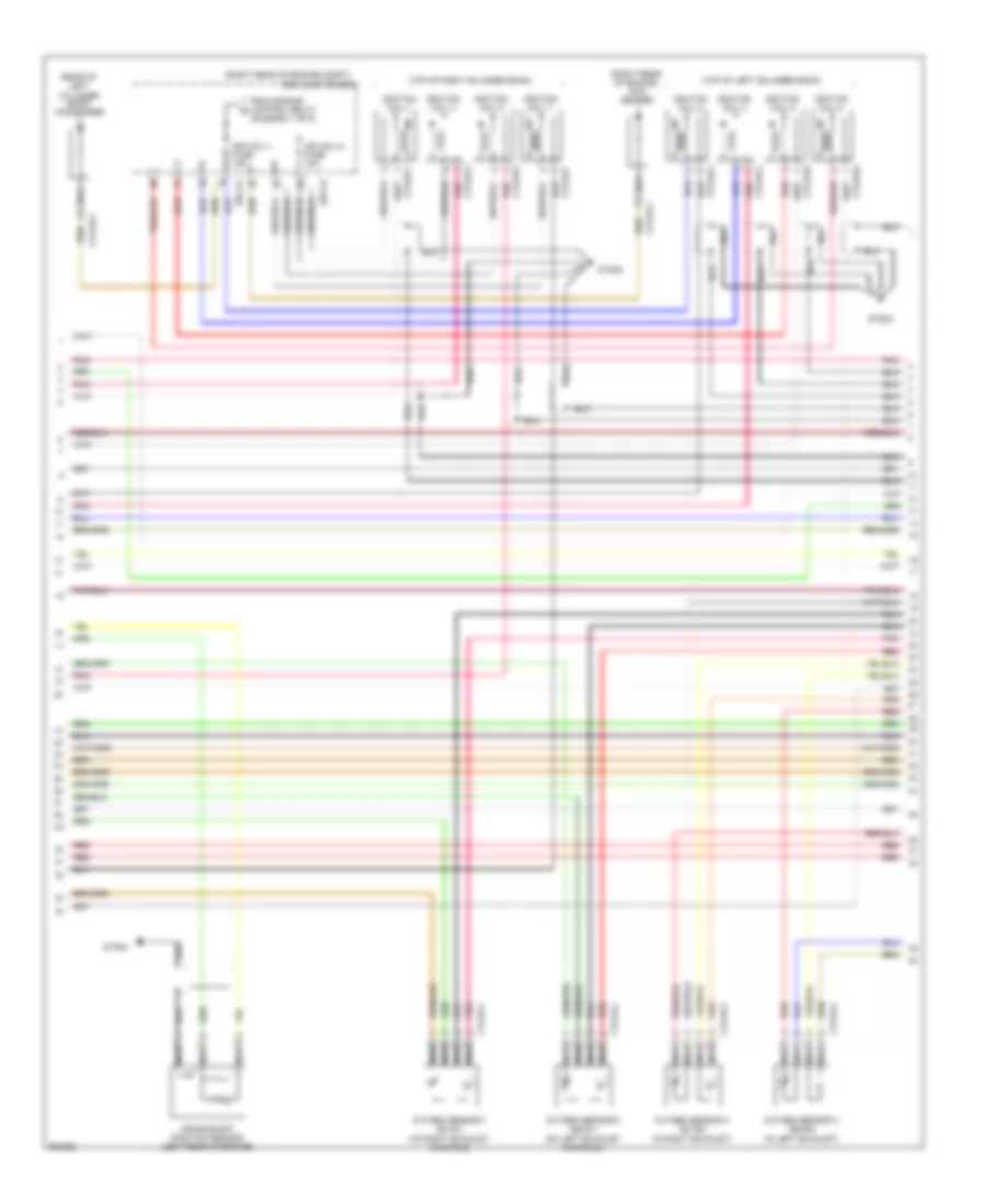
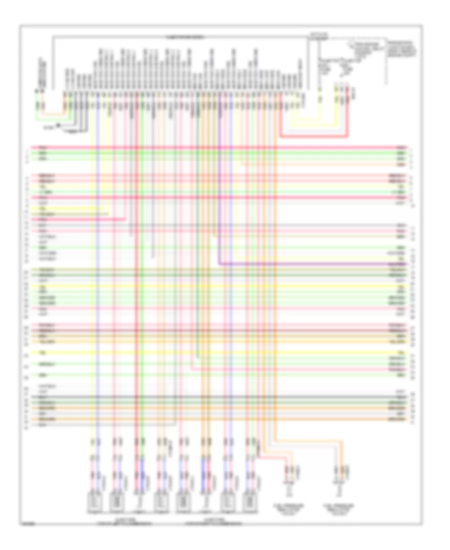
4.6L, Электросхема системы управления двигателя (2 из 5) для Hyundai Equus Ultimate 2012
 https://portal-diagnostov.com/license.html
Automotive Electricians Portal FZCO
Automotive Electricians Portal FZCO
https://portal-diagnostov.com/license.html
https://portal-diagnostov.com/license.html
Automotive Electricians Portal FZCO
Automotive Electricians Portal FZCO4.6L, Электросхема системы управления двигателя (2 из 5) для Hyundai Equus Ultimate 2012 - Список элементов:
- (front of left cylinder head)
- (front of right cylinder head)
- (front of trunk, near fuel tank) canister close valve
- (in air intake duct) mass air flow sensor
- (rear of engine) variable intake manifold valve
- (right front
- (top left side of engine) canister purge control solenoid valve
- (under left side of rear seat, in fuel tank)
- A/c pressure transducer (left front of engine compt)
- Accel pedal position sensor (behind accelerator pedal assembly)
- Afm
- Afs
- Ctg05-1
- Ctg05-2
- Ctg05-3
- Ctg05-4
- E/r-ca
- E/r-e2a
- Ec01
- Ef11
- Engine room junction box (right rear of engine compt)
- Etc motor
- Etc motor & throttle position sensor (throttle body)
- Fuel pump motor
- Fuel pump resistor
- Fuel sender
- Fuel sender & fuel pump motor
- Fuel tank pressure sensor (rear of trunk area)
- Gf03 (base of left "c" pillar)
- Gtg04
- Instrument cluster system
- Oil control valve 1 (intake)
- Oil control valve 2 (exhaust)
- Oil control valve 3 (intake)
- Oil control valve 4 (exhaust)
- Pnk
- Red
- Throttle position sensor
- Wheel well)
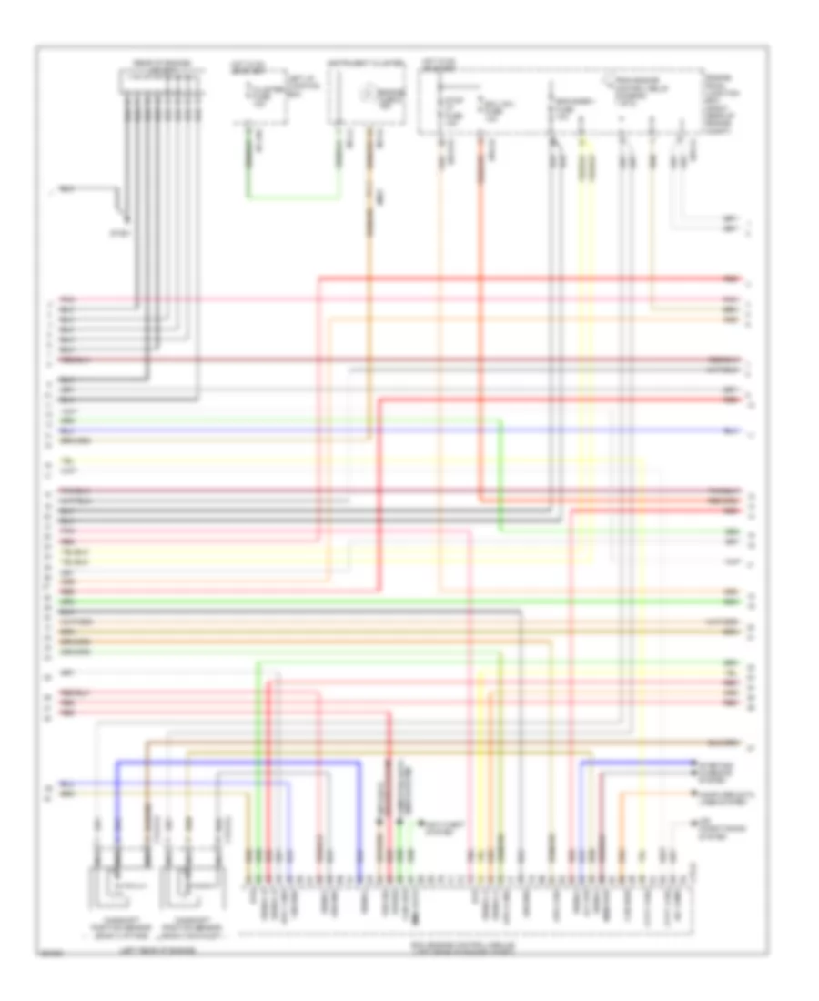
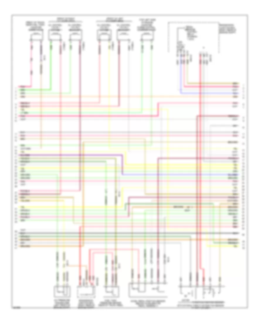
4.6L, Электросхема системы управления двигателя (3 из 5) для Hyundai Equus Ultimate 2012
 https://portal-diagnostov.com/license.html
Automotive Electricians Portal FZCO
Automotive Electricians Portal FZCO
https://portal-diagnostov.com/license.html
https://portal-diagnostov.com/license.html
Automotive Electricians Portal FZCO
Automotive Electricians Portal FZCO4.6L, Электросхема системы управления двигателя (3 из 5) для Hyundai Equus Ultimate 2012 - Список элементов:
- (diagram 1 of 5)
- (rear of left cylinder bank) condenser
- (right rear of engine compt)
- (right rear of engine) con- denser
- (top of left cylinder bank)
- (top of right cylinder bank)
- Crankshaft position sensor (left rear of engine)
- Ctg16-1
- Ctg16-2
- Ctg16-3
- Ctg16-4
- Ctg18-1
- Ctg18-2
- Ctg18-3
- Ctg18-4
- Ctg18-5
- Ctg18-6
- Ctg18-7
- Ctg18-8
- Ctg19-1
- Ctg19-2
- E/r junction box
- E/r-ca
- E/r-cb
- From engine control relay b
- Gtg02
- Gtg03
- Gtg04
- Ign coil-1 fuse 15a
- Ign coil-2 fuse 15a
- Ignition coil 1
- Ignition coil 2
- Ignition coil 3
- Ignition coil 4
- Ignition coil 5
- Ignition coil 6
- Ignition coil 7
- Ignition coil 8
- Nca
- Oxygen sensor 1 (b1/s1) (on right exhaust manifold)
- Oxygen sensor 2 (b2/s1) (on left exhaust manifold)
- Oxygen sensor 3 (b1/s2) (in right exhaust)
- Oxygen sensor 4 (b2/s2) (in left exhaust)
- Pnk
- Red
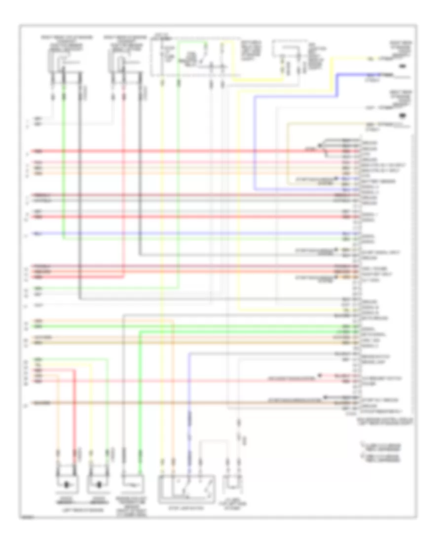
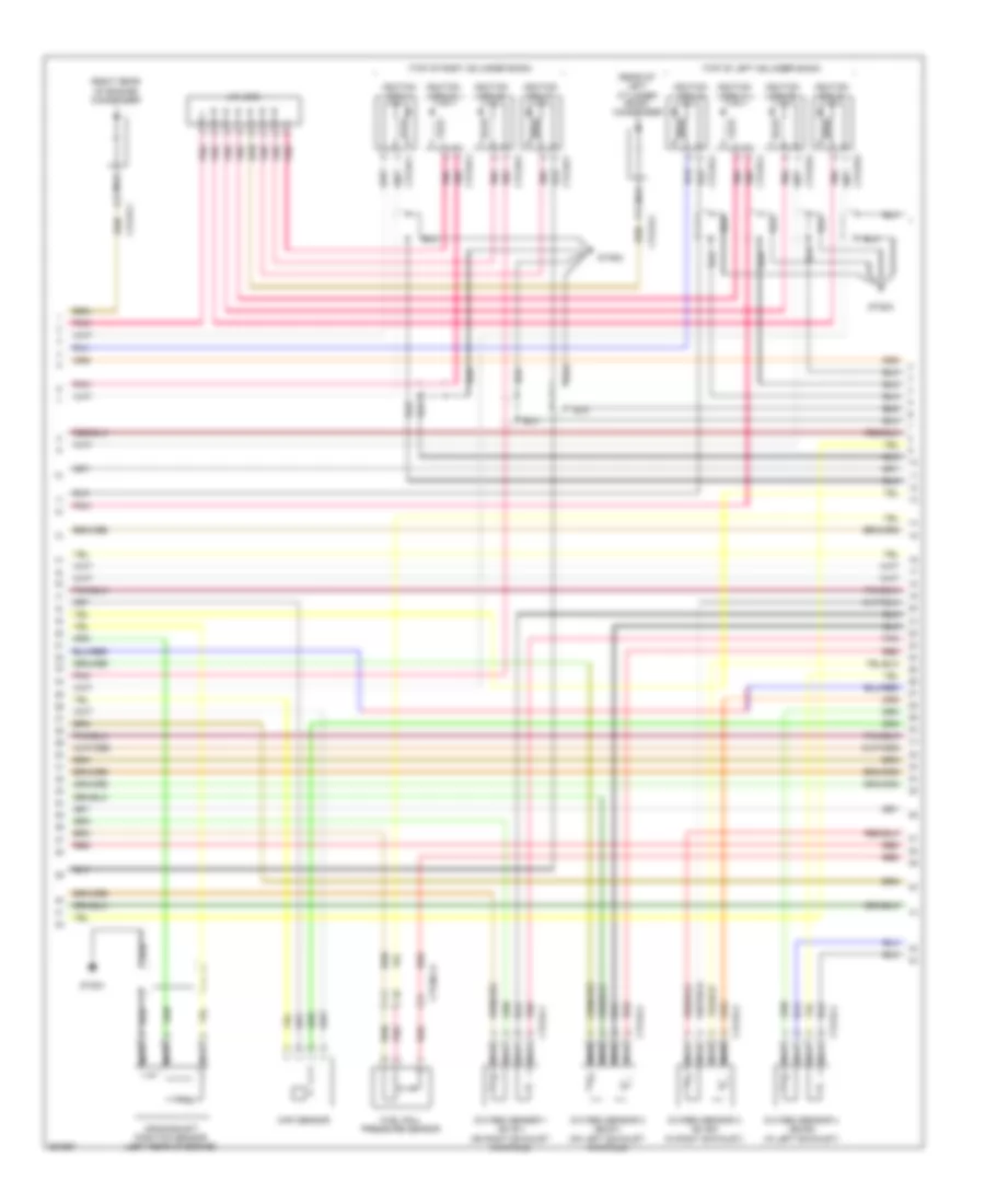
4.6L, Электросхема системы управления двигателя (4 из 5) для Hyundai Equus Ultimate 2012
 https://portal-diagnostov.com/license.html
Automotive Electricians Portal FZCO
Automotive Electricians Portal FZCO
https://portal-diagnostov.com/license.html
https://portal-diagnostov.com/license.html
Automotive Electricians Portal FZCO
Automotive Electricians Portal FZCO4.6L, Электросхема системы управления двигателя (4 из 5) для Hyundai Equus Ultimate 2012 - Список элементов:
- (left rear of engine)
- (rear of engine) j/c jc11
- A/c comp
- Air conditioning system
- Alt (fr)
- Anti-theft system
- Aps 1 gnd
- Aps 2 gnd
- Aps 2 sig
- Brakes system anti-lock
- Camshaft position sensor (bank 2 exhaust)
- Camshaft position sensor (bank 2 intake)
- Can high
- Can low
- Cluster fuse 10a
- Computer data lines system
- Ctg-k
- Ctg13-3
- Ctg13-4
- Cvvt 3 sig
- Cvvt 4 sig
- E/r-ca
- E/r-cb
- E/r-e1a
- Ecm (engine control module) (left rear of engine compt)
- Ecu (ig1) fuse 10a
- Em31
- Eng snsr-1 fuse 10a
- Engine check ind
- Engine room junction box (right rear of engine compt)
- From engine control relay (diagram 1 of 5)
- Ground
- Gtg01
- Hot in on or start
- Htr
- I/p-lhe
- Immo data
- Instrument cluster
- Left i/p junction box
- M11-a
- M11-b
- Mem pwr
- Nca
- Pnk
- Power
- Red
- Signal
- Signal a
- Signal b
- Starting/ charging system
- Stop lp fuse 10a
- Vss sig
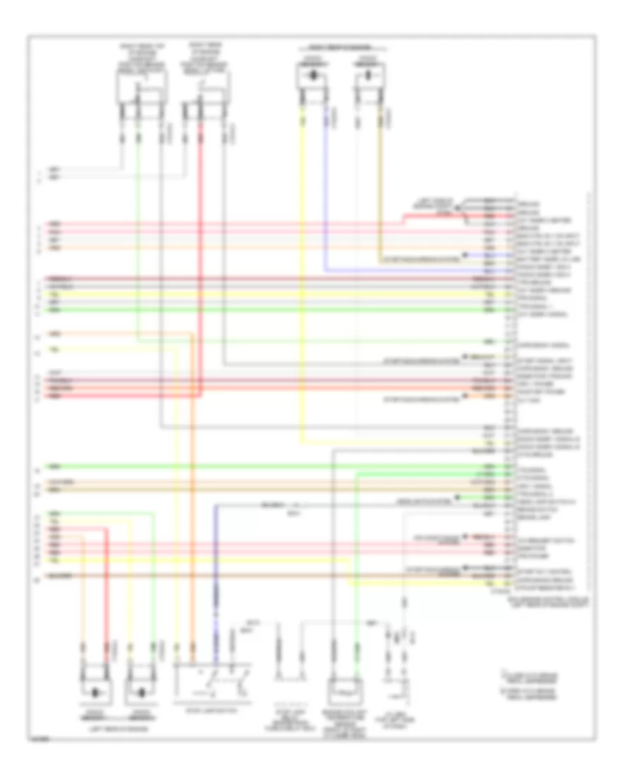
4.6L, Электросхема системы управления двигателя (5 из 5) для Hyundai Equus Ultimate 2012
 https://portal-diagnostov.com/license.html
Automotive Electricians Portal FZCO
Automotive Electricians Portal FZCO
https://portal-diagnostov.com/license.html
https://portal-diagnostov.com/license.html
Automotive Electricians Portal FZCO
Automotive Electricians Portal FZCO4.6L, Электросхема системы управления двигателя (5 из 5) для Hyundai Equus Ultimate 2012 - Список элементов:
- (left rear of engine)
- (right rear of engine)
- (right rear of engine compt)
- (right rear of engine) camshaft position sensor (bank 1 intake)
- (right rear top of engine) camshaft position sensor (bank 1 exhaust)
- A/c request switch
- Air conditioning system
- Alt (com)
- Aps 1 power
- Aps 1 sig
- Battery sensor
- Box
- Brake lamp
- Brake switch
- Close with brake a
- Ctg-k
- Ctg13-1
- Ctg13-2
- Ctg23-1
- Ctg23-2
- Ctg23-3
- Ctg23-4
- E/r
- E/r fuse & relay box (left side of engine compt)
- E/r-cb
- E/r-e2b
- Ec01
- Ecm (engine control module (left rear of engine compt)
- Ects ground
- Ects signal
- Eng ctrl rly input
- Eng ctrl rly on input
- Engine coolant temperature sensor (front of right cylinder head)
- F/pump resister rly
- Fuel pump
- Ground
- Gtg01
- Hot at all times
- Htr
- J/c je02 (top left side of dash)
- Junction
- Knock
- Knock sensor 2
- Knock sensor 4
- Nca
- On/start input
- Open with brake b
- Pedal depressed
- Pnk
- Power
- Red
- Relay
- Resistor
- Sensor 1
- Sensor 3
- Signal
- Signal 1
- Signal 2
- Signal a
- Signal b
- Start rly ground
- Start signal input
- Starting/charging system
- Stop lamp switch
- Stop lp fuse 10a
5.0L
5.0L, Электросхема системы управления двигателя (1 из 6) для Hyundai Equus Ultimate 2012
 https://portal-diagnostov.com/license.html
Automotive Electricians Portal FZCO
Automotive Electricians Portal FZCO
https://portal-diagnostov.com/license.html
https://portal-diagnostov.com/license.html
Automotive Electricians Portal FZCO
Automotive Electricians Portal FZCO5.0L, Электросхема системы управления двигателя (1 из 6) для Hyundai Equus Ultimate 2012 - Список элементов:
- (left rear of engine compt)
- (not used)
- Anti-theft system
- Apt ground
- Apt signal
- Ccp can high
- Ccp can low
- Ccv output
- Ckps signal a
- Ckps signal b
- Computer data lines system
- Cooling fans system
- Cruise control system
- Cruise ctrl signal
- Cruise sw ground
- Ctg-ag
- Cvvt 1 (intake) signal
- Cvvt 2 (ex) signal
- E/r fuse & relay box (left side of engine compt)
- E/r-ca
- E/r-cb
- E/r-e1a
- E/r-e2a
- E/r-e2b
- Ec41
- Ecm (engine control module)
- Ecu fuse 30a
- Ef11
- Eng ctrl rly ctrl
- Engine control relay
- Engine room junction box (right rear of engine compt)
- Engine speed in
- Etc motor (+)
- Etc motor (-)
- F/pump fuse 20a
- Fan ctrl module pwm
- Fps ground
- From snsr 3 fuse (diagram 5 of 6)
- Ftps gnd
- Ftps signal
- Fuel lvl in (middle)
- Fuel lvl in (total)
- Fuel pump motor
- Fuel pump relay
- Fuel pump resistor (right front wheel well)
- Fuel pump resistor relay
- Fuel pump rly ctrl
- Fuel sender
- Fuel sender & fuel pump motor (under left side of rear seat, in fuel tank)
- Gf03 (base of left "c" pillar)
- Hot at all times
- Ignition coil 1 ctrl
- Ignition coil 2 ctrl
- Ignition coil 3
- Ignition coil 4 ctrl
- Ignition coil 5 ctrl
- Ignition coil 6
- Ignition coil 7 ctrl
- Ignition coil 8 ctrl
- Immo ind control
- Ind control eng chk
- Injector 1 control
- Injector 2 control
- Injector 3 control
- Injector 4 control
- Injector 5 control
- Injector 6 control
- Injector 7 control
- Injector 8 control
- Instrument cluster system
- Map signal
- Map snsr gnd
- Oxygen snsr 1 ground
- Oxygen snsr 1 signal
- Oxygen snsr 2 ground
- Oxygen snsr 2 signal
- Pcsv output
- Pnk
- Power distribution system
- Red
- Snsr 2 fuse 10a
- To ign coil 1 fuse (diagram 3 of 6)
- To injector (b+) fuse (diagram 2 of 6)
- To snsr 3 fuse (diagram 5 of 6)
5.0L, Электросхема системы управления двигателя (2 из 6) для Hyundai Equus Ultimate 2012
 https://portal-diagnostov.com/license.html
Automotive Electricians Portal FZCO
Automotive Electricians Portal FZCO
https://portal-diagnostov.com/license.html
https://portal-diagnostov.com/license.html
Automotive Electricians Portal FZCO
Automotive Electricians Portal FZCO5.0L, Электросхема системы управления двигателя (2 из 6) для Hyundai Equus Ultimate 2012 - Список элементов:
- C-can high
- C-can low
- Computer data lines system
- Ctg-idb
- Ctg02-1
- Ctg02-2
- Ctg24-1
- Ctg24-2
- Ctg24-3
- Ctg24-4
- Ctg24-5
- Ctg24-6
- Ctg24-7
- Ctg24-8
- Ctginj-a
- Ctginj-b
- E/r-cb
- Engine room junction box (right rear of engine compt)
- From engine control relay (diagram 1 of 6)
- Fuel pressure regulator valve 1
- Fuel pressure regulator valve 2
- Ground
- Gtg01
- Hot in on or start
- Injector (b+) fuse 15a
- Injector (ig1) fuse 10a
- Injector 1 sig
- Injector 1 snsr gnd
- Injector 2 sig
- Injector 2 snsr gnd
- Injector 3 sig
- Injector 3 snsr gnd
- Injector 4 sig
- Injector 4 snsr gnd
- Injector 5 sig
- Injector 5 snsr gnd
- Injector 6 sig
- Injector 6 snsr gnd
- Injector 7 sig
- Injector 7 snsr gnd
- Injector 8 sig
- Injector 8 snsr gnd
- Injector control 1
- Injector control 2
- Injector control 3
- Injector control 4
- Injector control 5
- Injector control 6
- Injector control 7
- Injector control 8
- Injector drive box
- Injectors (top of left cylinder bank)
- Injectors (top of right cylinder bank)
- Msv1 high
- Msv1 low
- Msv1 on
- Msv1 sel0
- Msv1 sel1
- Msv2 high
- Msv2 low
- Msv2 on
- Msv2 sel0
- Msv2 sel1
- On/start input
- Pnk
- Red
5.0L, Электросхема системы управления двигателя (3 из 6) для Hyundai Equus Ultimate 2012
 https://portal-diagnostov.com/license.html
Automotive Electricians Portal FZCO
Automotive Electricians Portal FZCO
https://portal-diagnostov.com/license.html
https://portal-diagnostov.com/license.html
Automotive Electricians Portal FZCO
Automotive Electricians Portal FZCO5.0L, Электросхема системы управления двигателя (3 из 6) для Hyundai Equus Ultimate 2012 - Список элементов:
- (front of left cylinder head)
- (front of right cylinder head)
- (front of trunk, near fuel tank) canister close valve
- (top left side of engine)
- 1 of 6)
- A/c pressure transducer (left front of engine compt)
- Accel pedal position sensor (behind accelerator pedal assembly)
- Canister purge control solenoid valve
- Control relay (diagram
- Ctg05-1
- Ctg05-2
- Ctg05-3
- Ctg05-4
- E/r-ca
- E/r-cb
- E/r-e2a
- Ec41
- Ef11
- Engine room junction box (right rear of engine compt)
- Etc motor & throttle position sensor (throttle body)
- From engine b
- Fuel tank pressure sensor (rear of trunk area)
- Ign coil 1 fuse 20a
- Motor
- Oil control valve 1 (intake)
- Oil control valve 2 (exhaust)
- Oil control valve 3 (intake)
- Oil control valve 4 (exhaust)
- Pnk
- Red
- Throttle position sensor
5.0L, Электросхема системы управления двигателя (4 из 6) для Hyundai Equus Ultimate 2012
 https://portal-diagnostov.com/license.html
Automotive Electricians Portal FZCO
Automotive Electricians Portal FZCO
https://portal-diagnostov.com/license.html
https://portal-diagnostov.com/license.html
Automotive Electricians Portal FZCO
Automotive Electricians Portal FZCO5.0L, Электросхема системы управления двигателя (4 из 6) для Hyundai Equus Ultimate 2012 - Список элементов:
- (rear of left cylinder bank) condenser
- (right rear of engine) condenser
- (top of left cylinder bank)
- (top of right cylinder bank)
- Crankshaft position sensor (left rear of engine)
- Ctg16-1
- Ctg16-2
- Ctg16-3
- Ctg16-4
- Ctg18-1
- Ctg18-2
- Ctg18-3
- Ctg18-4
- Ctg18-5
- Ctg18-6
- Ctg18-7
- Ctg18-8
- Ctg19-1
- Ctg19-2
- Ctginj-a
- Fuel rail pressure sensor
- Gtg01
- Gtg02
- Gtg03
- Ignition coil 1
- Ignition coil 2
- Ignition coil 3
- Ignition coil 4
- Ignition coil 5
- Ignition coil 6
- Ignition coil 7
- Ignition coil 8
- J/c jc32
- Map sensor
- Nca
- Oxygen sensor 1 (b1/s1) (on right exhaust manifold)
- Oxygen sensor 2 (b2/s1) (on left exhaust manifold)
- Oxygen sensor 3 (b1/s2) (in right exhaust)
- Oxygen sensor 4 (b2/s2) (in left exhaust)
- Pnk
- Red
5.0L, Электросхема системы управления двигателя (5 из 6) для Hyundai Equus Ultimate 2012
 https://portal-diagnostov.com/license.html
Automotive Electricians Portal FZCO
Automotive Electricians Portal FZCO
https://portal-diagnostov.com/license.html
https://portal-diagnostov.com/license.html
Automotive Electricians Portal FZCO
Automotive Electricians Portal FZCO5.0L, Электросхема системы управления двигателя (5 из 6) для Hyundai Equus Ultimate 2012 - Список элементов:
- (left rear of engine)
- A/c comp cut sig
- Air conditioning system
- Alt fr
- Anti- theft system
- Apm 1 ground
- Apm 2 ground
- Apm 2 signal
- Battery power
- Brakes system anti-lock
- C-can high
- C-can low
- Camshaft position sensor (bank 2 exhaust)
- Camshaft position sensor (bank 2 intake)
- Check ind
- Cluster fuse 10a
- Cmps bank1 signal
- Cmps bank2 ex sig
- Cmps bank2 ground
- Cmps bank2 signal
- Computer data lines
- Computer data lines system
- Ctg-kg
- Ctg13-3
- Ctg13-4
- Cvvt 3 intake sig
- Cvvt 4 ex sig
- E/r-ca
- E/r-cb
- E/r-e1a
- Ec41
- Ecm (engine control module) (left rear of engine compt)
- Ecu (b+) fuse 15a
- Ecu (ig1) fuse 10a
- Em31
- Em41
- Engine
- Engine room junction box (right rear of engine compt)
- From engine control relay (diagram 1 of 6)
- Gtg01
- Hot at all times
- Hot in on or start
- I/p-lhe
- I/p-lhf
- Immo data line
- Instrument cluster
- J/c jc31
- Knock snsr 2 sig a
- Knock snsr 2 sig b
- Knock snsr 4 sig a
- Knock snsr 4 sig b
- Left i/p junction box
- M11-a
- M11-b
- Msv 1 on
- Msv 1 sel 0
- Msv 1 sel 1
- Msv 2 on
- Msv 2 sel 0
- Msv 2 sel 1
- Nca
- Oxy snsr 1 htr
- Oxy snsr 3 signal
- Oxy snsr 4 ground
- Oxy snsr 4 htr
- Pdm 1 fuse 10a
- Pnk
- Red
- Snsr 1 fuse 10a
- Snsr 3 fuse 10a
- Starting/ charging system
- Stop lamp fuse 10a
- System
- To fuel pump relay (diagram 1 of 6)
- Wheel spd sig
5.0L, Электросхема системы управления двигателя (6 из 6) для Hyundai Equus Ultimate 2012
 https://portal-diagnostov.com/license.html
Automotive Electricians Portal FZCO
Automotive Electricians Portal FZCO
https://portal-diagnostov.com/license.html
https://portal-diagnostov.com/license.html
Automotive Electricians Portal FZCO
Automotive Electricians Portal FZCO5.0L, Электросхема системы управления двигателя (6 из 6) для Hyundai Equus Ultimate 2012 - Список элементов:
- (left rear of engine)
- (left side of engine compt) gtg01
- (right rear
- (right rear of engine)
- (right rear top
- A/c request switch
- Air conditioning system
- Alt com
- Apm 1 power
- Apm 1 signal
- Battery snsr lin line
- Brake lamp
- Brake switch
- Camshaft position sensor (bank 1 intake)
- Close with brake a
- Cmps bank1 ground
- Cmps bank1 signal
- Cmps bank2 ground
- Ctg-kg
- Ctg13-1
- Ctg13-2
- Ctg23-1
- Ctg23-2
- Ctg23-3
- Ctg23-4
- Ec41
- Ecm (engine control module) (left rear of engine compt)
- Em31
- Eng ctrl rly on input
- Engine coolant temperature sensor (front of right cylinder head)
- F/pump resister rly
- Fps power
- Fps signal
- Ground
- Head lamp switch in
- Headlights system
- Its signal
- J/c je02 (top left side of dash)
- Knock sensor 1
- Knock sensor 2
- Knock sensor 3
- Knock sensor 4
- Knock snsr 1 sig a
- Knock snsr 1 signal b
- Knock snsr 3 sig a
- Knock snsr 3 signal b
- Nca
- Of engine)
- Of engine) camshaft position sensor (bank 1 exhaust)
- On/start power
- Open with brake b
- Oxy snsr 2 heater
- Oxy snsr 3 ground
- Oxy snsr 3 heater
- Oxy snsr 4 signal
- Pedal depressed
- Pnk
- Red
- Snsr pwr
- Snsr pwr (tps/map)
- Start rly control
- Start signal input
- Starting/charging system
- Stop lamp relay (engine room fuse & relay box)
- Stop lamp switch
- Tps ground
- Tps signal 1
- Tps signal 2
- Wts ground
- Wts signal

 Čeština
 Dansk
Dansk Deutsch
 Ελληνικά
 English
 English
 Español
 Suomi
Suomi Français
 Français
 עברית
עברית Hrvatski
 Magyar
 Italiano
 日本語
日本語 한국어
한국어 Nederlands
 Polski
 Português
 Português
 Română
 Русский
 Slovenčina
 Slovenščina
 Svenska
 中文 (中国)
