СИСТЕМА УПРАВЛЕНИЯ ДВИГАТЕЛЯ
3.5L
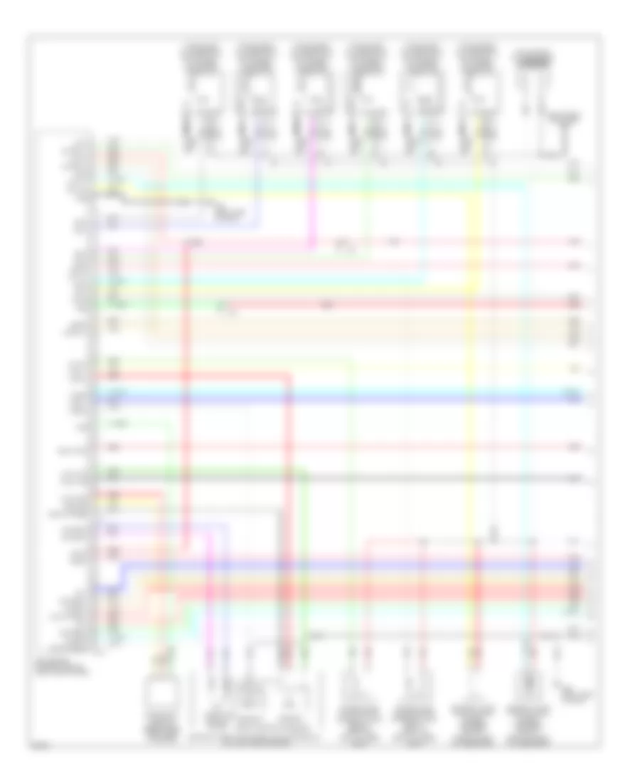
3.5L, Электросхема системы управления двигателя (1 из 4) для Infiniti EX35 2011
 https://portal-diagnostov.com/license.html
Automotive Electricians Portal FZCO
Automotive Electricians Portal FZCO
https://portal-diagnostov.com/license.html
https://portal-diagnostov.com/license.html
Automotive Electricians Portal FZCO
Automotive Electricians Portal FZCO
3.5L, Электросхема системы управления двигателя (1 из 4) для Infiniti EX35 2011 - Список элементов:
- (front of right cylinder bank)
- (right front of engine) f34
- (top of left cylinder bank) ignition coil 2 (w/ power transistor)
- (top of left cylinder bank) ignition coil 4 (w/ power transistor)
- (top of left cylinder bank) ignition coil 6 (w/ power transistor)
- (top of right cylinder bank) condenser
- (top of right cylinder bank) ignition coil 1 (w/ power transistor)
- (top of right cylinder bank) ignition coil 3 (w/ power transistor)
- (top of right cylinder bank) ignition coil 5 (w/ power transistor)
- Af+1
- Af-1
- Afh1
- Afh2
- Avcc phase 1
- Avcc phase 2
- Avcc pos
- Avcc tps
- Close
- Crankshaft position sensor (pos) (right rear of engine)
- Cvtc 1
- Cvtc 2
- E phase 1
- E phase 2
- Ecm (engine control module) (right end of dash)
- Electric throttle control actuator (bank 2) (top left side of engine)
- Evap
- Evtc 1
- Evtc 2
- Exhaust valve timing control magnet retarder (bank 1) (front of right cylinder bank)
- Exhaust valve timing control magnet retarder (bank 2) (front of left cylinder bank)
- F101
- F102
- Fpr
- Gnd
- Gnd a(tps)
- Gnd pos
- Gnda intpres
- Ign 1
- Ign 2
- Ign 3
- Ign 4
- Ign 5
- Ign 6
- Ignsw
- Intake valve timing control solenoid valve (bank 1)
- Intake valve timing control solenoid valve (bank 2) (front of left cylinder bank)
- M95 (right side of dash)
- Motor1 1
- Motor1 2
- Motor2 1
- Motor2 2
- Motrly1
- Nca
- O2hr1
- O2hr2
- Open
- Phase 1
- Phase 2
- Plug spark
- Pnk
- Pos
- Red
- Sensor 1
- Sensor 2
- Spark plug
- Ssoff
- Tan
- Throttle control motor
- Throttle position sensor
- Tps1 1
- Tps1 2
- Tps2 1
- Tps2 2
- Vmot1
- Vmot2
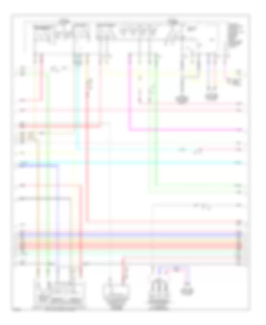
3.5L, Электросхема системы управления двигателя (2 из 4) для Infiniti EX35 2011
 https://portal-diagnostov.com/license.html
Automotive Electricians Portal FZCO
Automotive Electricians Portal FZCO
https://portal-diagnostov.com/license.html
https://portal-diagnostov.com/license.html
Automotive Electricians Portal FZCO
Automotive Electricians Portal FZCO3.5L, Электросхема системы управления двигателя (2 из 4) для Infiniti EX35 2011 - Список элементов:
- A/t assembly (on transmission)
- Can h
- Can l
- Close
- Computer data lines system
- Cooling fans system
- Cpu
- E106
- E22 (right rear of engine compt)
- Ecm relay
- Electric throttle control actuator (bank 1) (top right side of engine)
- Evap canister purge volume control solenoid valve (top rear of engine)
- F1 e3
- F103
- Fuel pump relay
- Fuse 10a
- Fuse 15a
- Hot at all times
- Ignition relay
- Ipdm e/r (intelligent power distribution module engine room) (right rear of engine compt)
- Joint connector
- M116
- Nca
- Open
- Pnk
- Red
- Sensor 1
- Sensor 2
- St rly
- Tan
- Tcm (transmission control module)
- Throttle control motor
- Throttle control motor relay
- Throttle position sensor
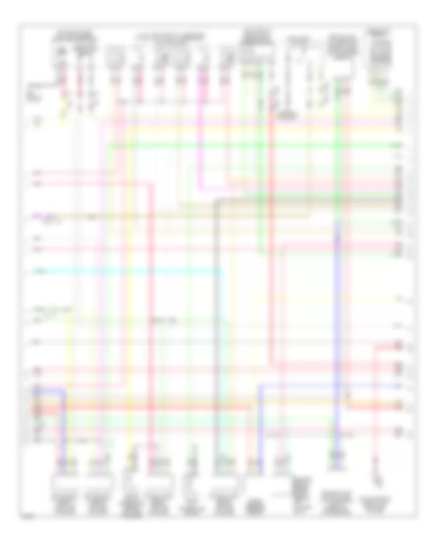
3.5L, Электросхема системы управления двигателя (3 из 4) для Infiniti EX35 2011
 https://portal-diagnostov.com/license.html
Automotive Electricians Portal FZCO
Automotive Electricians Portal FZCO
https://portal-diagnostov.com/license.html
https://portal-diagnostov.com/license.html
Automotive Electricians Portal FZCO
Automotive Electricians Portal FZCO3.5L, Электросхема системы управления двигателя (3 из 4) для Infiniti EX35 2011 - Список элементов:
- (1, 3 & 5: top of right cylinder bank) (2, 4 & 6: top of left cylinder bank) fuel injectors
- (left front of engine compt) mass air flow sensor (bank 2)
- (rear of right cylinder bank) exhaust valve timing control position sensor (bank 1)
- (top of fuel tank) fuel level sensor unit & fuel pump (main)
- Air fuel ratio (a/f) sensor 1 (bank 1) (right side of engine)
- Air fuel ratio (a/f) sensor 1 (bank 2) (left side of engine)
- B24 (left "c" pillar)
- Camshaft position sensor (phase) (bank 2) (rear of left cylinder bank)
- Combination meter
- Comm amp lcd
- Comm amp mtr
- Comm lcd amp
- Comm mtr amp
- E104
- E106
- Engine coolant temperature sensor (left rear of engine)
- Engine oil temperature sensor
- Exhaust valve timing control position sensor (bank 2) (rear of left cylinder bank)
- F1 e3
- F103
- Fuel pump
- Fuel tank temperature sensor
- Heated oxygen sensor 2 (bank 1) (left side of engine)
- Heated oxygen sensor 2 (bank 2) (left side of engine)
- M116
- M170 m134
- M95 (right side of dash)
- Nca
- Pnk
- Power steering control unit (right side of dash)
- Power steering pressure sensor
- Red
- Snow mode switch
- Tacho eng
- Tan
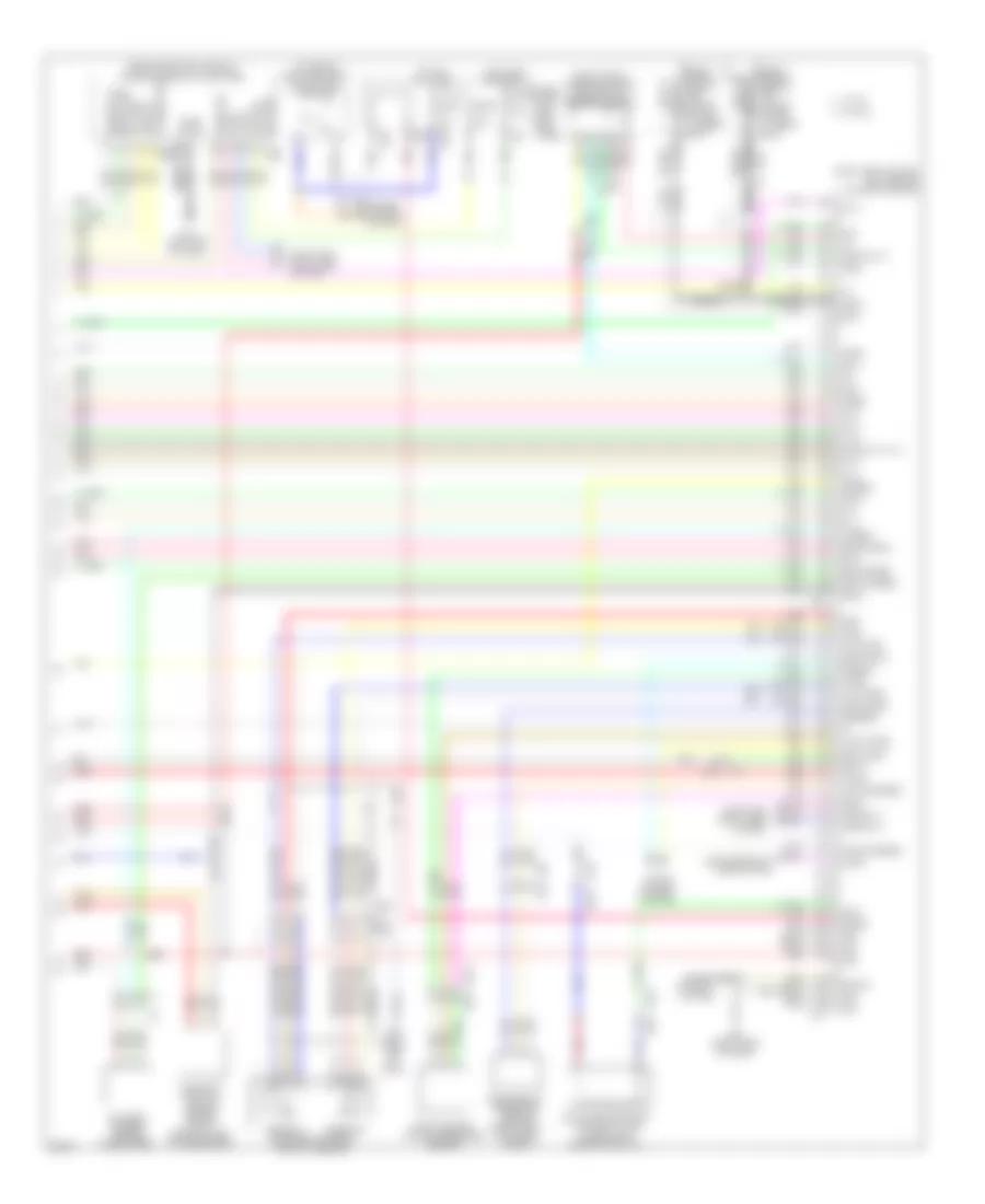
3.5L, Электросхема системы управления двигателя (4 из 4) для Infiniti EX35 2011
 https://portal-diagnostov.com/license.html
Automotive Electricians Portal FZCO
Automotive Electricians Portal FZCO
https://portal-diagnostov.com/license.html
https://portal-diagnostov.com/license.html
Automotive Electricians Portal FZCO
Automotive Electricians Portal FZCO3.5L, Электросхема системы управления двигателя (4 из 4) для Infiniti EX35 2011 - Список элементов:
- (behind center console) unified meter & a/c amplifier
- (on brake pedal bracket) stop lamp switch
- (or pnk)
- (or red)
- (right end of dash) ecm (engine control module)
- (right front of engine compt) mass air flow sensor (bank 1)
- Accelerator pedal position sensor
- Af+2
- Af-2
- Amp lcd
- Amp meter
- Aps1
- Aps2
- Ascdsw
- At snow sw
- Avcc aps1
- Avcc aps2
- Avcc ftprs
- Avcc pdpress
- B201
- Bat pwr
- Batt
- Battery current sensor (on battery)
- Bnc sw
- Brake
- Camshaft position sensor (phase) (bank 1) (rear of right cylinder bank)
- Can h
- Can l
- Cdcv
- Computer data lines system
- Cruise control system
- Cursen
- E103
- E106
- Evap canister vent control valve (under right rear of vehicle)
- Evap control system pressure sensor
- F102
- F103
- F103 m116
- F201 f9
- Ftprs
- Fuse 10a
- Fuse block (j/b) (left kick panel)
- Gnd
- Gnd a
- Gnd a(aps1)
- Gnd a(aps2)
- Gnd phase 2
- Gnd pspres
- Gnda ascd
- Gnda cursen
- Gnda o2 tw to
- Gnda pdpress
- Gnda qa ta
- Hot at all times
- Hot in on or start
- Ign pwr
- Inj 1
- Inj 2
- Inj 3
- Inj 4
- Inj 5
- Inj 6
- Kline
- Knk1
- Knk2
- Knock sensor (bank 1) (top center of right cylinder bank)
- Knock sensor (bank 2) (top center of left cylinder bank)
- Lcd amp
- M107
- M11 (left end of dash)
- M116
- M117
- M66
- M67
- M95 (right side of dash)
- Meter amp
- Neut h
- O2sr1
- O2sr2
- Pdpress
- Pnk
- Pspres
- Qa1+
- Qa2+
- Red
- Refrigerant pressure sensor (right front of engine compt)
- Sens gnd
- Sensor 1
- Sensor 2
- Shield
- Ta+2
- Ta1
- Tacho
- Tan
- To1
- Vbr
- Vehcan h1
- Vehcan l1
- W/ icc
- W/o icc

 Čeština
 Dansk
Dansk Deutsch
 Ελληνικά
 English
 English
 Español
 Suomi
Suomi Français
 Français
 עברית
עברית Hrvatski
 Magyar
 Italiano
 日本語
日本語 한국어
한국어 Nederlands
 Polski
 Português
 Português
 Română
 Русский
 Slovenčina
 Slovenščina
 Svenska
 中文 (中国)