POWER DISTRIBUTION
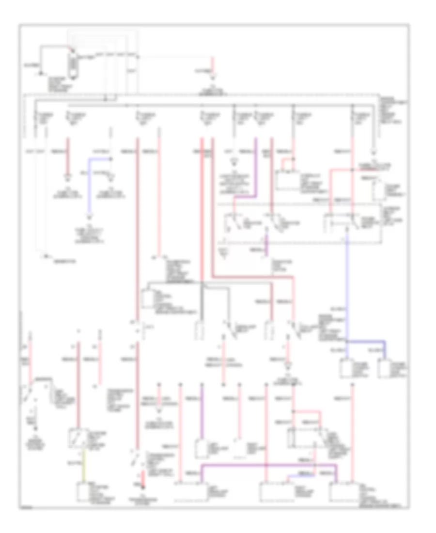
Power Distribution Wiring Diagram (1 of 4) for Dodge Avenger ES 1997
 https://portal-diagnostov.com/license.html
Automotive Electricians Portal FZCO
Automotive Electricians Portal FZCO
https://portal-diagnostov.com/license.html
https://portal-diagnostov.com/license.html
Automotive Electricians Portal FZCO
Automotive Electricians Portal FZCO
List of elements for Power Distribution Wiring Diagram (1 of 4) for Dodge Avenger ES 1997:
- A40
- Asd relay (left side of safety wall)
- Battery
- Drl control unit (canada) (left front of engine compartment)
- Engine compartment relay box (engine compt. relay box)
- Engine compartment relay box (left front of engine compartment)
- Fusible link 1 120a
- Fusible link 2 60a
- Fusible link 3 40a
- Fusible link 4 40a
- Fusible link 5 30a
- Fusible link 6 30a
- Fusible link 7 50a
- Fusible link 8 30a
- Generator
- Headlamp relay
- Hi radiator fan
- High beam relay (canada) (left front of engine compt.)
- Hydraulic unit (left front of engine compartment)
- Interior relay box (left side of i/p)
- J/c 4
- Left headlamp (canada)
- Left headlamp (usa)
- Lo radiator fan
- Power seat assembly
- Power window main switch
- Power window sub switch
- Power windows relay
- Powertrain control module (left front of engine compartment)
- Radiator fan motor
- Red
- Red/
- Right headlamp (canada)
- Right headlamp (usa)
- Starter (a/t) motor (right front of engine)
- Starter motor (right front of engine)
- Starter relay (a/t) (center of i/p)
- Taillamp relay
- To engine controls system
- To fuse 1,5,6,10,11 (j/b) cavity 1, conn b-62 (diagram 3 of 4)
- To fuse 10 (f/b) (diagram 2 of 4)
- To fuse 4 (f/b) (diagram 2 of 4)
- To fuse 5 & 6 (f/b) (diagram 2 of 4)
- To fuse 7 (f/b) (diagram 2 of 4)
- To fuse 8 (f/b) (diagram 2 of 4)
- To fuses 1,2 & 3 (f/b) (diagram 2 of 4)
- To junction block cavity 7 & ignition switch cavity 1 (diagram 4 of 4)
- To transmissions system
- Transmission control module (a/t) (left shock tower)
- Transmission control relay (a/t) (left side of safety wall)
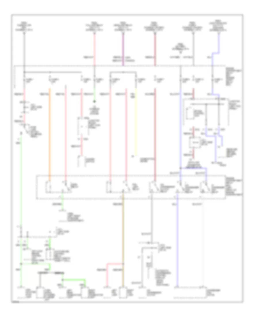
Power Distribution Wiring Diagram (2 of 4) for Dodge Avenger ES 1997
 https://portal-diagnostov.com/license.html
Automotive Electricians Portal FZCO
Automotive Electricians Portal FZCO
https://portal-diagnostov.com/license.html
https://portal-diagnostov.com/license.html
Automotive Electricians Portal FZCO
Automotive Electricians Portal FZCOList of elements for Power Distribution Wiring Diagram (2 of 4) for Dodge Avenger ES 1997:
- (canada)
- (usa)
- A/c compressor clutch
- A/c compressor clutch relay
- Anti-lock brake control unit (right side of i/p)
- Auto-cruise control relay (right side of safety wall)
- Automatic compressor control module (dohc) (right kick panel)
- Avenger
- B-42
- B-43
- B-49
- B-54
- B-57
- B-63
- Combination meter
- Condenser fan motor
- Data link connector (center of i/p)
- Engine compartment relay box (engine compt. relay box)
- Engine compartment relay box (left front of engine compartment)
- Etacs control unit
- Fog lamp relay
- From battery (diagram 1 of 4)
- From fuse 2 (fusible link box) (diagram 1 of 4)
- From fusible link box (diagram 1 of 4)
- From headlamp relay cavity 4 (diagram 1 of 4)
- From junction block cavity 5, conn b-63 (diagram 3 of 4)
- From taillamp relay cavity 4 (diagram 1 of 4)
- Fuse 1 20a
- Fuse 10 10a
- Fuse 11 10a
- Fuse 2 15a
- Fuse 3 15a
- Fuse 4 15a
- Fuse 5 15a
- Fuse 6 10a
- Fuse 7 10a
- Fuse 8 20a
- Hazard switch
- Hi condenser fan relay
- High- mounted stop lamp
- Horn (left front of engine compartment)
- Horn relay
- J/c 1 (left side of i/p)
- J/c 2 (left side of i/p)
- Junction block (left kick panel)
- Left fog lamp
- Left rear combination light
- Lo condenser fan relay
- Radio
- Receiver (behind driver's seat)
- Red
- Right fog lamp
- Right rear combination light
- Sebring
- Stop lamp switch (on brake pedal)
- To interior lights system
- Turn signal & hazard flasher unit
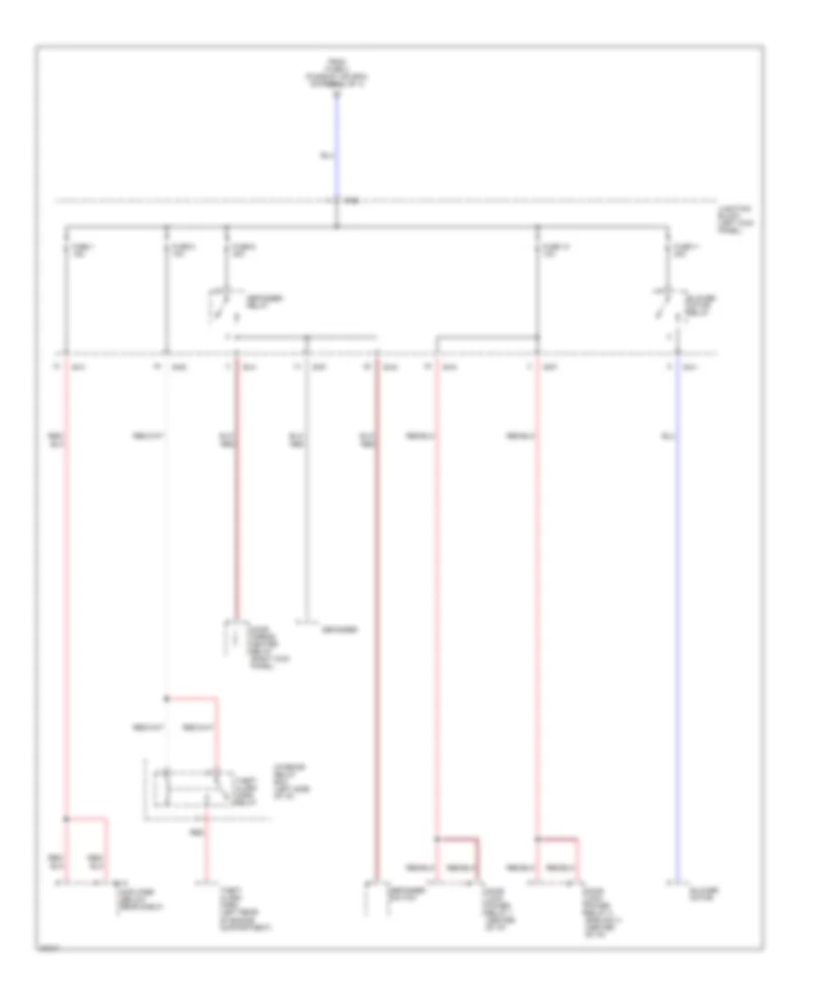
Power Distribution Wiring Diagram (3 of 4) for Dodge Avenger ES 1997
 https://portal-diagnostov.com/license.html
Automotive Electricians Portal FZCO
Automotive Electricians Portal FZCO
https://portal-diagnostov.com/license.html
https://portal-diagnostov.com/license.html
Automotive Electricians Portal FZCO
Automotive Electricians Portal FZCOList of elements for Power Distribution Wiring Diagram (3 of 4) for Dodge Avenger ES 1997:
- Amplifier (below rear shelf)
- B-41
- B-42
- B-43
- B-52
- B-57
- B-62
- Blower motor
- Blower motor relay
- Defogger
- Defogger relay
- Defogger switch
- Door lock power relay 1 (center of i/p)
- Door lock power relay 2 (rke only) (center of i/p)
- Door mirror heater relay (right kick panel)
- E-12
- From fuse 2 (fusible link box) (diagram 1 of 4)
- Fuse 1 15a
- Fuse 10 10a
- Fuse 11 30a
- Fuse 5 10a
- Fuse 6 30a
- Interior relay box (left side of i/p)
- Junction block (left kick panel)
- Red
- Red/
- Theft alarm horn (left rear of engine compartment)
- Theft alarm horn relay
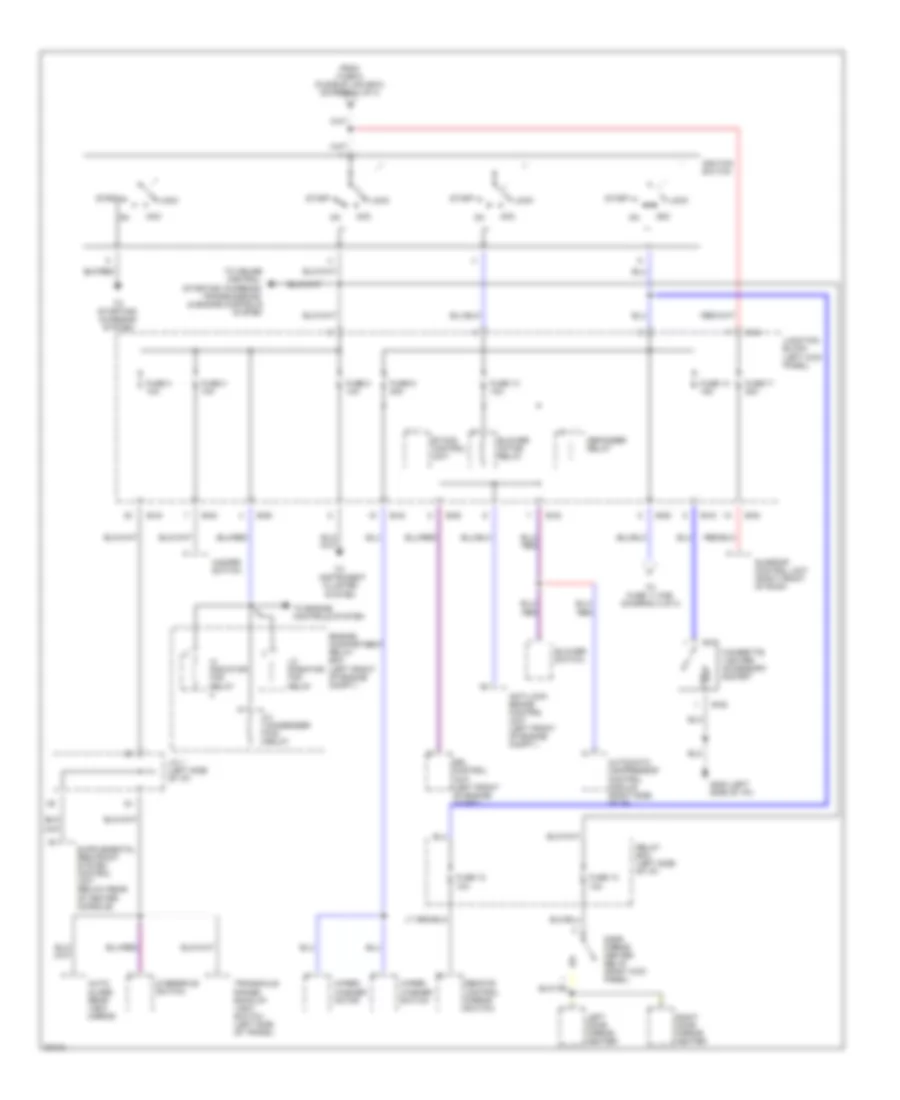
Power Distribution Wiring Diagram (4 of 4) for Dodge Avenger ES 1997
 https://portal-diagnostov.com/license.html
Automotive Electricians Portal FZCO
Automotive Electricians Portal FZCO
https://portal-diagnostov.com/license.html
https://portal-diagnostov.com/license.html
Automotive Electricians Portal FZCO
Automotive Electricians Portal FZCOList of elements for Power Distribution Wiring Diagram (4 of 4) for Dodge Avenger ES 1997:
- (left
- Acc
- Anti-lock brake control unit (left front of engine compt.)
- Auto- glare rear view mirror
- Automatic compressor control module (right side of i/p)
- B-27
- B-28
- B-41
- B-42
- B-43
- B-54
- B-63
- Blower motor relay
- Blower switch
- Cigarette lighter/ accessory socket
- Defogger relay
- Door mirror heater relay (right kick panel)
- Drl control unit (left front of engine compt.)
- Engine compartment relay box (left front of engine compt.)
- Etacs control unit
- From fuse 5 (fusible link box) (diagram 1 of 4)
- Fuse 12 10a
- Fuse 13 10a
- Fuse 14 15a
- Fuse 17 20a
- Fuse 3 10a
- Fuse 4 10a
- Fuse 8 10a
- Fuse 9 20a
- G202 side of i/p))
- Hazard switch
- Hi condenser fan relay
- Hi radiator fan relay
- Ignition switch
- J/c 1 (left side of i/p)
- Junction block (left kick panel)
- Left door mirror heater
- Lo radiator fan relay
- Lock
- Overdrive switch
- Red
- Relay box (left side of i/p)
- Remote control mirror switch
- Right door mirror heater
- Start
- Sunroof control unit (right front of roof)
- To cruise control, starting/ charging, transmissions, & engine controls system
- To engine controls system
- To fuse 11 (f/b) (diagram 2 of 4)
- To instrument cluster system
- To starting/ charging system
- Transaxle range/ back-up light switch (left side of trans.)
- Wiper/ washer motor
- Wiper/ washer switch

 Čeština
 Dansk
Dansk Deutsch
 Ελληνικά
 English
 English
 Español
 Suomi
Suomi Français
 Français
 עברית
עברית Hrvatski
 Magyar
 Italiano
 日本語
日本語 한국어
한국어 Nederlands
 Polski
 Português
 Português
 Română
 Русский
 Slovenčina
 Slovenščina
 Svenska
 中文 (中国)
