SUPPLEMENTAL RESTRAINTS
Supplemental Restraint Wiring Diagram for Dodge Neon High Line 2000
 https://portal-diagnostov.com/license.html
Automotive Electricians Portal FZCO
Automotive Electricians Portal FZCO
https://portal-diagnostov.com/license.html
https://portal-diagnostov.com/license.html
Automotive Electricians Portal FZCO
Automotive Electricians Portal FZCO
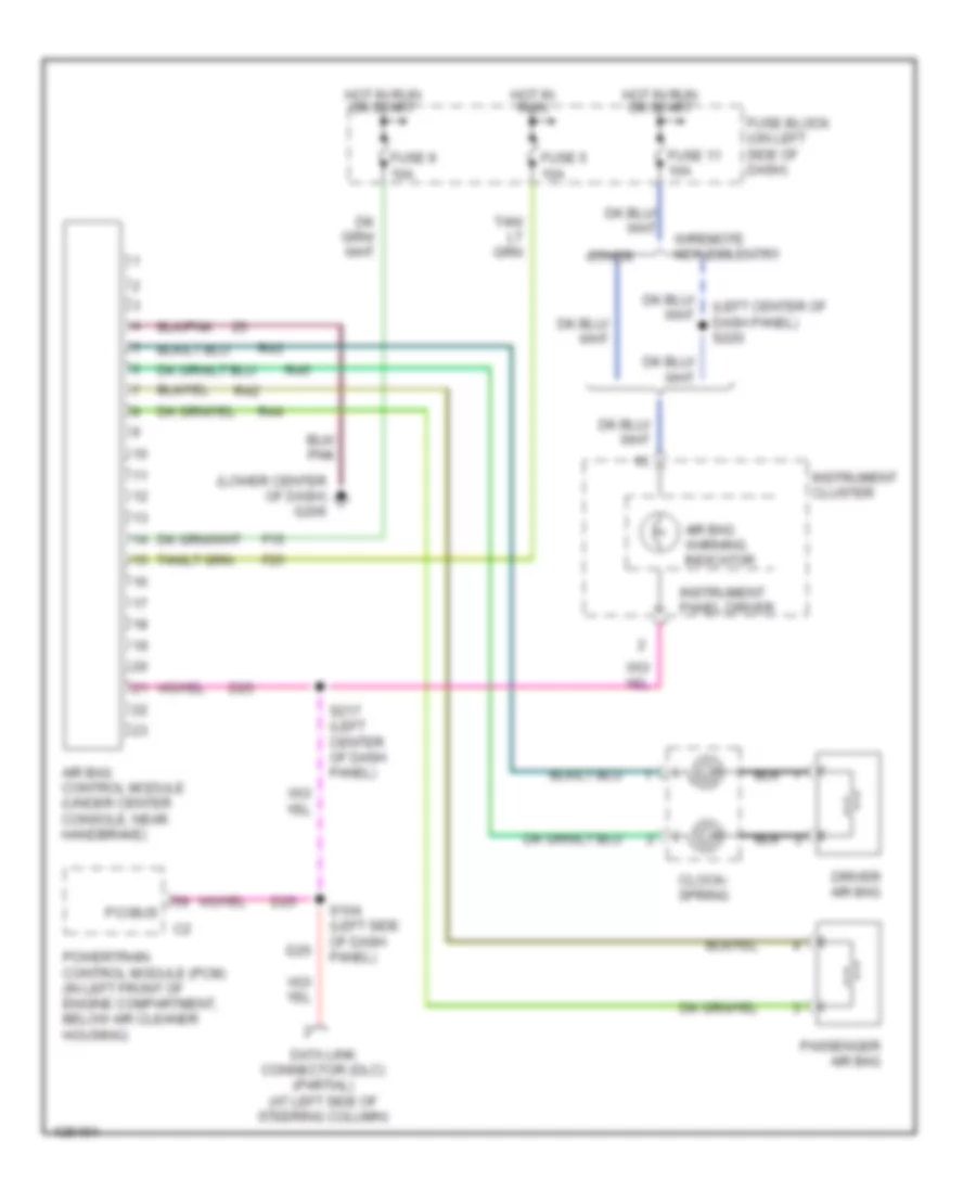
List of elements for Supplemental Restraint Wiring Diagram for Dodge Neon High Line 2000:
- (left center of dash panel) s220
- (lower center of dash) g206
- Air bag control module (under center console, near handbrake)
- Air bag warning indicator
- Clock- spring
- D25
- Data link connector (dlc) (partial) (at left side of steering column)
- Driver air bag
- F15
- F25
- Fuse 11 10a
- Fuse 5 10a
- Fuse 9 10a
- Fuse block (on left side of dash)
- Hot in run
- Hot in run or start
- Instrument cluster
- Instrument panel driver
- Other
- Passenger air bag
- Pci bus
- Powertrain control module (pcm) (in left front of engine compartment, below air cleaner housing)
- R42
- R43
- R44
- R45
- S104 (left side of dash panel)
- S217 (left center of dash panel)
- W/remote keyless entry
 Čeština
 Dansk
Dansk Deutsch
 Ελληνικά
 English
 English
 Español
 Suomi
Suomi Français
 Français
 עברית
עברית Hrvatski
 Magyar
 Italiano
 日本語
日本語 한국어
한국어 Nederlands
 Polski
 Português
 Português
 Română
 Русский
 Slovenčina
 Slovenščina
 Svenska
 中文 (中国)
 Türkçe
