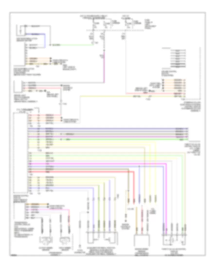
CRUISE CONTROL
Cruise Control Wiring Diagram for Audi Q7 Premium Plus 2013
 https://portal-diagnostov.com/license.html
Automotive Electricians Portal FZCO
Automotive Electricians Portal FZCO
https://portal-diagnostov.com/license.html
https://portal-diagnostov.com/license.html
Automotive Electricians Portal FZCO
Automotive Electricians Portal FZCO
List of elements for Cruise Control Wiring Diagram for Audi Q7 Premium Plus 2013:
- (behind left side of dash) g664
- 11a
- 12 pin connector
- 3.0l sc
- 3.0l turbo diesel
- 3.ol turbo diesel
- Accelerator pedal position sensor & accelerator pedal position sensor 2 (accelerator pedal assembly)
- Brake light switch & brake pedal switch (brake pedal assembly)
- Computer data lines system
- Cruise control switch (if equipped)
- Distance regulation control module (if equipped) (behind right front bumper)
- Distance regulation sensor heater
- Engine control module (right rear of engine compt)
- Engine controls system
- Engine speed sensor (transmission bell housing)
- Fuse 10a
- Fuse 5a
- Fuse carrier
- Fuse panel b (left instrument panel)
- G44 (behind left kick panel)
- G640 (left side of engine compt)
- Hot at all times
- Input speed sensor
- Nca
- Output speed sensor
- Red
- Steering column electronic systems control module (in steering column assembly)
- T105
- T10c
- T10d
- T10e
- T16a
- T60
- T8c
- T91
- T94
- Throttle valve control module (3.0l sc) (on supercharger)
- Throttle valve control module (3.0l turbo diesel) (on throttle valve)
- Transmission assembly
- Transmission control module (w/o mechatronic: under front passenger's seat) (w/ mechatronic: in transmission)
 Čeština
 Dansk
Dansk Deutsch
 Ελληνικά
 English
 English
 Español
 Suomi
Suomi Français
 Français
 עברית
עברית Hrvatski
 Magyar
 Italiano
 日本語
日本語 한국어
한국어 Nederlands
 Polski
 Português
 Português
 Română
 Русский
 Slovenčina
 Slovenščina
 Svenska
 中文 (中国)
 Türkçe
