AIR CONDITIONING
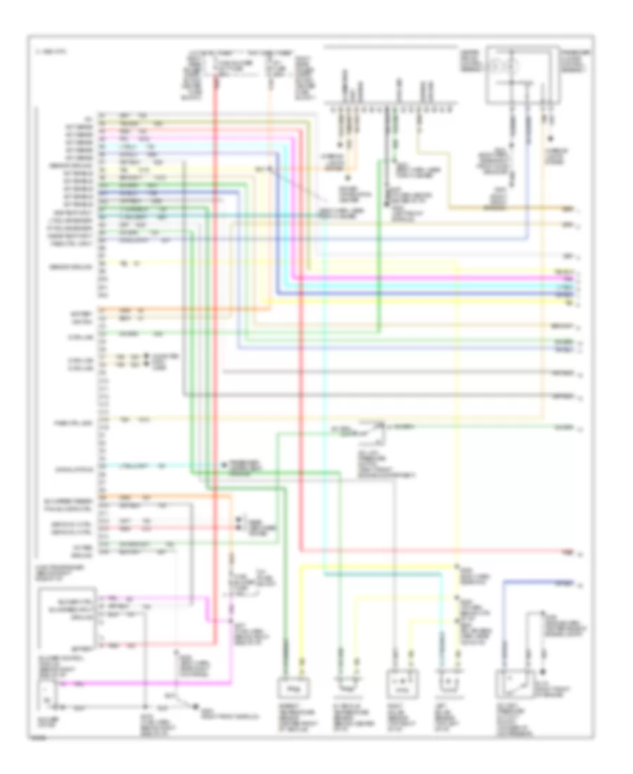
Air Conditioning Wiring Diagrams (1 of 2) for Oldsmobile Aurora 1997
 https://portal-diagnostov.com/license.html
Automotive Electricians Portal FZCO
Automotive Electricians Portal FZCO
https://portal-diagnostov.com/license.html
https://portal-diagnostov.com/license.html
Automotive Electricians Portal FZCO
Automotive Electricians Portal FZCO
List of elements for Air Conditioning Wiring Diagrams (1 of 2) for Oldsmobile Aurora 1997:
- (body harn, near turn flasher)
- (right front shroud)
- +5v
- A/c high pressure cut-out switch (on rear of compressor)
- A/c low pressure switch (right front engine compartment)
- A/c req
- A10
- A11
- A12
- Act enable
- Act sense
- Amb temp input
- Ambient temperature sensor (center front of vehicle)
- B tan
- B10
- B11
- B12
- Battery
- Blower control module (behind right side of i/p)
- Blower ctrl
- Blower motor
- Blw speed feedbk
- Blw speed input
- C 1995 vftc
- C10
- C11
- C12
- C13
- C14
- C15
- C16
- Computer data lines
- D10
- D11
- D12
- D13
- D14
- D15
- D16
- Data line
- Defog rly ctrl
- Driver information center
- G119 (right front of engine)
- G200 (left front shroud)
- G203
- G203 (right front shroud)
- Ground
- Heater and a/c control assembly
- Hot at all times
- Hvac blower fuse 10a
- Hvac blower mot fuse 30a
- Hvac programmer (behind right side of i/p)
- I/p 1 fuse 10a
- I/p fuse block
- Ignition
- Illumination
- In-vehicle temperature sensor (behind center of i/p)
- Inside temp input
- Interior lights system
- Left solar sensor (top left of i/p)
- Lt solar sensor
- Pass ctrl gnd
- Pass ctrl input
- Passenger climate control assembly
- Passenger heated seat module
- Pwm blw spd ctrl
- Rear defogger system
- Red
- Right rear power distri- bution center fuse block 1
- Right rear power distri- bution center fuse block 2
- Right solar sensor (top right of i/p)
- Rt solar sensor
- S106 (engine harn, center rear of engine compt)
- S211
- S212
- S225 (body harn, near right kick panel)
- S229 (i/p harn, behind ctr of i/p)
- S231 (body harn, near turn flasher)
- S276 (hvac harn, behind right side of i/p)
- S277 (hvac harn, behind right side of i/p)
- S285 (body harn, near pcm)
- S288 (solar sens harn, near top of i/p)
- Sensor ground
- Signal status
- Tan
- Uart
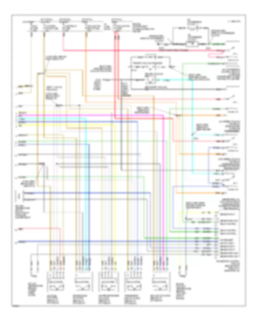
Air Conditioning Wiring Diagrams (2 of 2) for Oldsmobile Aurora 1997
 https://portal-diagnostov.com/license.html
Automotive Electricians Portal FZCO
Automotive Electricians Portal FZCO
https://portal-diagnostov.com/license.html
https://portal-diagnostov.com/license.html
Automotive Electricians Portal FZCO
Automotive Electricians Portal FZCOList of elements for Air Conditioning Wiring Diagrams (2 of 2) for Oldsmobile Aurora 1997:
- (behind i/p, on plenum)
- (body harn, near right rear fender)
- (body harn, near secondary cooling fan motor)
- (body harn, rear center of engine compartment)
- (body, 144.5 cm from pcm)
- (engine harn, near a/c compressor clutch)
- (hvac harn, behind right side of i/p)
- A/c compressor clutch
- A/c compressor clutch diode
- A/c compressor control relay d (in engine compartment power distributon center)
- A/c high temperature switch (right front of engine compartment)
- A/c low temperature sensor (under wiper motor)
- A/c mode actuator (behind i/p, on plenum)
- A/c request
- Air inlet actuator (behind i/p, on plenum)
- C 1995 vftc
- Cooling fan fuse 60a
- Cooling fan relay fuse 10a
- Driver's side actuator (behind i/p, on plenum)
- Engine compartment power distribution center
- Engine coolant temperature sensor (top left side of
- Engine)
- Flat pack motor fuse 10a
- G103 (right front strut tower)
- Heater/defroster actuator (behind i/p, on plenum)
- High speed cooling fan relay (in engine compt power dist center relay block 1)
- Hot at all
- Hot in run
- Hvac relay fuse 10a
- I/p fuse block
- Ign 3 fuse 10a
- Low speed cooling fan relay (rear center of engine compartment)
- Nca
- Or start
- Passenger's side actuator
- Pnk
- Powertrain control module (behind right side of i/p, near shroud)
- Primary cooling fan
- Primary cooling fan diode
- Red
- Relay control
- S104
- S105
- S108
- S115 (body harn, right rear fender)
- S121
- S123
- S141
- S143
- S259
- S274
- S275
- S278
- Secondary cooling fan
- Sensor ground
- Sensor input
- Series/parallel cooling fan relay (in engine compt power dist center relay block 1)
- Solid state
- Switch input
- Times

 Čeština
 Dansk
Dansk Deutsch
 Ελληνικά
 English
 English
 Español
 Suomi
Suomi Français
 Français
 עברית
עברית Hrvatski
 Magyar
 Italiano
 日本語
日本語 한국어
한국어 Nederlands
 Polski
 Português
 Português
 Română
 Русский
 Slovenčina
 Slovenščina
 Svenska
 中文 (中国)
