BODY CONTROL MODULES
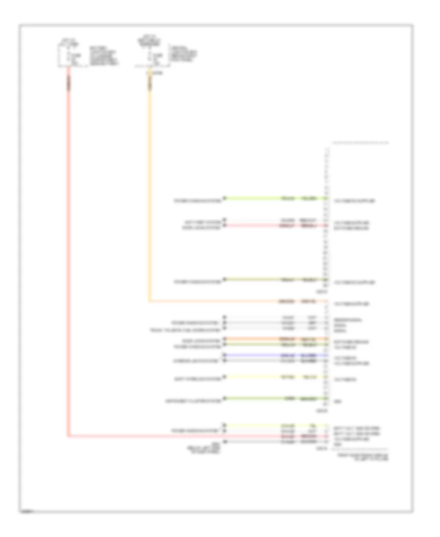
Body Control Modules Wiring Diagram (1 of 4) for Ford Thunderbird 2005
 https://portal-diagnostov.com/license.html
Automotive Electricians Portal FZCO
Automotive Electricians Portal FZCO
https://portal-diagnostov.com/license.html
https://portal-diagnostov.com/license.html
Automotive Electricians Portal FZCO
Automotive Electricians Portal FZCO
List of elements for Body Control Modules Wiring Diagram (1 of 4) for Ford Thunderbird 2005:
- (in left "a" pillar)
- 10-ag15
- 29-dk20
- 29s-dk21
- 31-aj81
- 31-dk20
- 31-dk20a
- 31-dk20b
- 31-dk20c
- 31-dk20d
- 31s-dk21
- 31s-ld9
- 31s-le15
- 31s-le16
- 31s-le22
- 31s-le23
- 31s-lf16
- 31s-lf17
- 31s-lf7
- 31s-lf8
- 31s-lg11
- 31s-lg18
- 4-eg11
- 5-eg11
- 7-aj81
- 8-ag15
- 8-ce9
- 8-gc21
- 8-gc7
- 8-gc8
- 8-gl7
- 9-ce9
- 91s-gj7
- A/c demand signal
- Battery junction box (in luggage compt, near battery)
- C201a
- C201b
- C201c
- C270d
- Central junction box (behind right kick panel)
- Computer data lines system
- Door locks system
- Exterior lights system
- Front electronic module
- Fuse 10a
- Fuse 5a
- G202 (at left "a" pillar)
- Gnd
- Headlights system
- Horns system
- Hot at all times
- Hot w/ ssp 2 relay energized
- Instrument cluster system
- Power steering valve solenoid (on lower left rear of engine compt)
- Power tops system
- Power windows system
- S407 (in body main harness, in breakout to p93)
- Scp+
- Scp-
- Sens sig rtn
- Sensor signal
- Ssp 4 relay
- Switched ground
- To rear electronic module (diagram 4 of 4)
- Vbatt
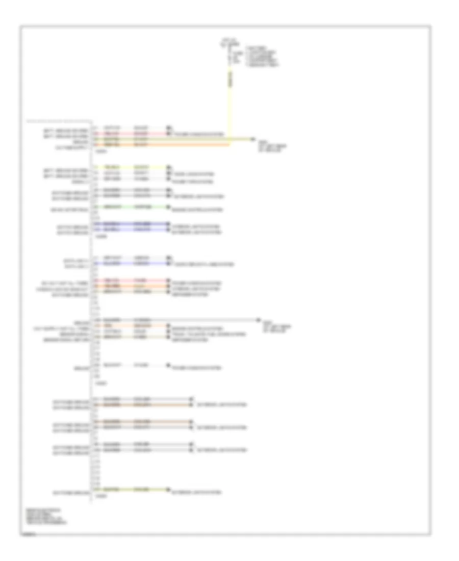
Body Control Modules Wiring Diagram (2 of 4) for Ford Thunderbird 2005
 https://portal-diagnostov.com/license.html
Automotive Electricians Portal FZCO
Automotive Electricians Portal FZCO
https://portal-diagnostov.com/license.html
https://portal-diagnostov.com/license.html
Automotive Electricians Portal FZCO
Automotive Electricians Portal FZCOList of elements for Body Control Modules Wiring Diagram (2 of 4) for Ford Thunderbird 2005:
- 10-aj81
- 29s-dk22
- 30-aa79
- 30-aj80
- 30s-gl46
- 30s-gl47
- 31-aj80
- 31-lc10
- 32-aj26
- 33-aj26
- 64s-lh2
- 7s-aj16
- 7s-aj40
- 7s-aj41
- 7s-ta33
- 8-aa30
- 8-aj81
- 9-rp9
- Anti-theft system
- Batt volt, gnd or open
- Battery junction box (in luggage compartment, near battery)
- C201d
- C201e
- C201g
- C270b
- Central junction box (behind right kick panel)
- Door locks system
- Front electronic module (in left "a" pillar)
- Fuse 10a
- Fuse 30a
- G204 (below left side of dash panel)
- Gnd
- Hot at all times
- Hot w/ ssp 2 relay energized
- Instrument cluster system
- Interior lights system
- Power windows system
- Sensor signal
- Shift interlock system
- Signal
- Switched ground
- Trunk, tailgate, fuel doors system
- Voltage dc
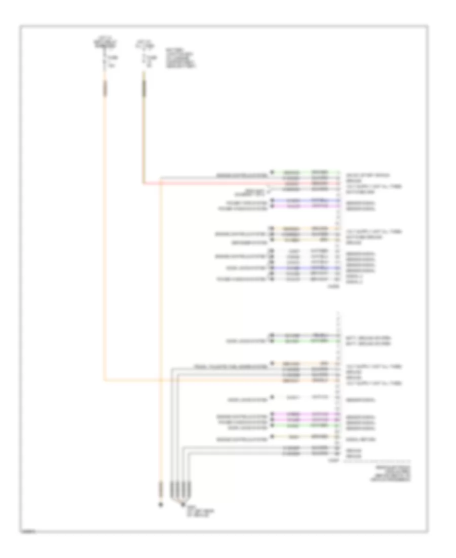
Body Control Modules Wiring Diagram (3 of 4) for Ford Thunderbird 2005
 https://portal-diagnostov.com/license.html
Automotive Electricians Portal FZCO
Automotive Electricians Portal FZCO
https://portal-diagnostov.com/license.html
https://portal-diagnostov.com/license.html
Automotive Electricians Portal FZCO
Automotive Electricians Portal FZCOList of elements for Body Control Modules Wiring Diagram (3 of 4) for Ford Thunderbird 2005:
- 10-ag24
- 15-rp12b
- 29s-dk30
- 30-aj71
- 31-aj71
- 31-aj82
- 31-dk30h
- 31s-lb25
- 31s-lf10
- 31s-lf11
- 31s-lf19
- 31s-lf20
- 31s-lf21
- 31s-lg14
- 31s-lg16
- 31s-lg21
- 31s-lg6
- 31s-lg9
- 32-aa11
- 32-aj27
- 33-aa10
- 33-aj27
- 4-eg12a
- 5-eg12a
- 7-aj82
- 7-lh1
- 8-gl20
- 9-hb23
- 91s-hb23
- Batt, ground or open
- Battery junction box (in luggage compartment, near battery)
- C420a
- C420b
- C420c
- C420d
- Computer data lines system
- Data link (+)
- Data link (-)
- Dc volt (hot all times)
- Defogger system
- Door locks system
- Engine controls system
- Exterior lights system
- Fuse 30a
- G402 (at left rear of vehicle)
- Ground
- Hot at all times
- Ign sw (start/run)
- Interior lights system
- Power tops system
- Power windows system
- Rear electronic module (rem) (behind seats, on vehicle crossbeam)
- Sensor signal
- Sensor signal return
- Signal 2
- Switch ground
- Switched ground
- Trunk, tailgate, fuel doors system
- Window/lock sw bias out
Body Control Modules Wiring Diagram (4 of 4) for Ford Thunderbird 2005
 https://portal-diagnostov.com/license.html
Automotive Electricians Portal FZCO
Automotive Electricians Portal FZCO
https://portal-diagnostov.com/license.html
https://portal-diagnostov.com/license.html
Automotive Electricians Portal FZCO
Automotive Electricians Portal FZCOList of elements for Body Control Modules Wiring Diagram (4 of 4) for Ford Thunderbird 2005:
- 10-aj18
- 10-aj82
- 15s-dk32
- 15s-rg2a
- 29s-aa83
- 29s-dk31
- 30-dk31
- 31-dk30c
- 31-dk30d
- 31-dk30e
- 31-dk30f
- 31-dk30g
- 31s-dk30
- 31s-rg2a
- 32-aa21
- 33-aa20
- 8-aa10
- 8-aa11
- 8-aa20
- 8-aa21
- 8-ag16
- 8-aj18
- 8-aj82
- 8-ga25
- 8-ga7
- 8-re32
- 9-ga1
- 91-hb24
- Batt, ground or open
- Battery junction box (in luggage compartment, near battery)
- C420e
- C420f
- Defogger system
- Door locks system
- Engine controls system
- From s407 a (diagram 1 of 4)
- Fuse 15a
- Fuse 5a
- G402 (at left rear of vehicle)
- Ground
- Hot at all times
- Hot w/ ssp 4 relay energized
- Ign sw (start or run)
- Power tops system
- Power windows system
- Rear electronic module (rem) (behind seats, on vehicle crossbeam)
- Sensor signal
- Signal 2
- Signal return
- Switched gnd
- Switched ground
- Trunk, tailgate, fuel doors system

 Čeština
 Dansk
Dansk Deutsch
 Ελληνικά
 English
 English
 Español
 Suomi
Suomi Français
 Français
 עברית
עברית Hrvatski
 Magyar
 Italiano
 日本語
日本語 한국어
한국어 Nederlands
 Polski
 Português
 Português
 Română
 Русский
 Slovenčina
 Slovenščina
 Svenska
 中文 (中国)
