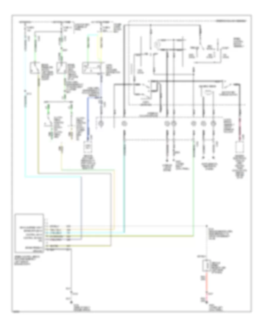
CRUISE CONTROL
Cruise Control Wiring Diagram for Ford Pickup F150 1997
 https://portal-diagnostov.com/license.html
Automotive Electricians Portal FZCO
Automotive Electricians Portal FZCO
https://portal-diagnostov.com/license.html
https://portal-diagnostov.com/license.html
Automotive Electricians Portal FZCO
Automotive Electricians Portal FZCO
List of elements for Cruise Control Wiring Diagram for Ford Pickup F150 1997:
- (main harn, near breakout to clockspring assembly) s230
- (main harn, near breakout to instrument cluster) s231
- 15a
- 20a
- A/t
- Accel
- Brake on/off (boo) switch (behind left side of i/p)
- Brake press in
- Brake pressure switch (left rear corner of engine compt)
- C233
- C234
- C239
- C242
- C257
- Clock- spring assembly (top of steering column)
- Clutch pedal position (ccp) switch (on clutch pedal arm)
- Clutch pedal position (ccp) switch jumper (left side of i/p)
- Coast
- Control sw gnd
- Control sw in
- Driver's airbag
- Fuse 13
- Fuse 5
- G105 (rear of right fender apron)
- G200 (lower left cowl panel)
- G203 (lower right cowl panel)
- Generic electronic module (gem)/ central timer module (ctm) (behind center of i/p)
- Ground
- Horn relay (in power distribution box)
- Horn switches
- Hot at all times
- Hot in run
- Hrn rly
- Ign
- Ignition key warning switch
- Interior lights system
- Junction box fuse/relay panel
- M/t
- Nca
- Off
- Ohms
- Power distri- bution box
- Remote anti-theft personality (rap) module (behind left side of i/p)
- Resume
- S102
- S107
- S112
- S143 (engine sensor harn, near breakout to vapor management valve)
- S221
- Set/
- Speed control servo/ amplifier assembly (left side of engine compt)
- Speed control switch assembly
- Steering column assembly
- Steering column ground
- Vehicle speed input
- Vehicle speed sensor (vss) (left rear of trans)
 Čeština
 Dansk
Dansk Deutsch
 Ελληνικά
 English
 English
 Español
 Suomi
Suomi Français
 Français
 עברית
עברית Hrvatski
 Magyar
 Italiano
 日本語
日本語 한국어
한국어 Nederlands
 Polski
 Português
 Português
 Română
 Русский
 Slovenčina
 Slovenščina
 Svenska
 中文 (中国)
 Türkçe
