POWER DISTRIBUTION
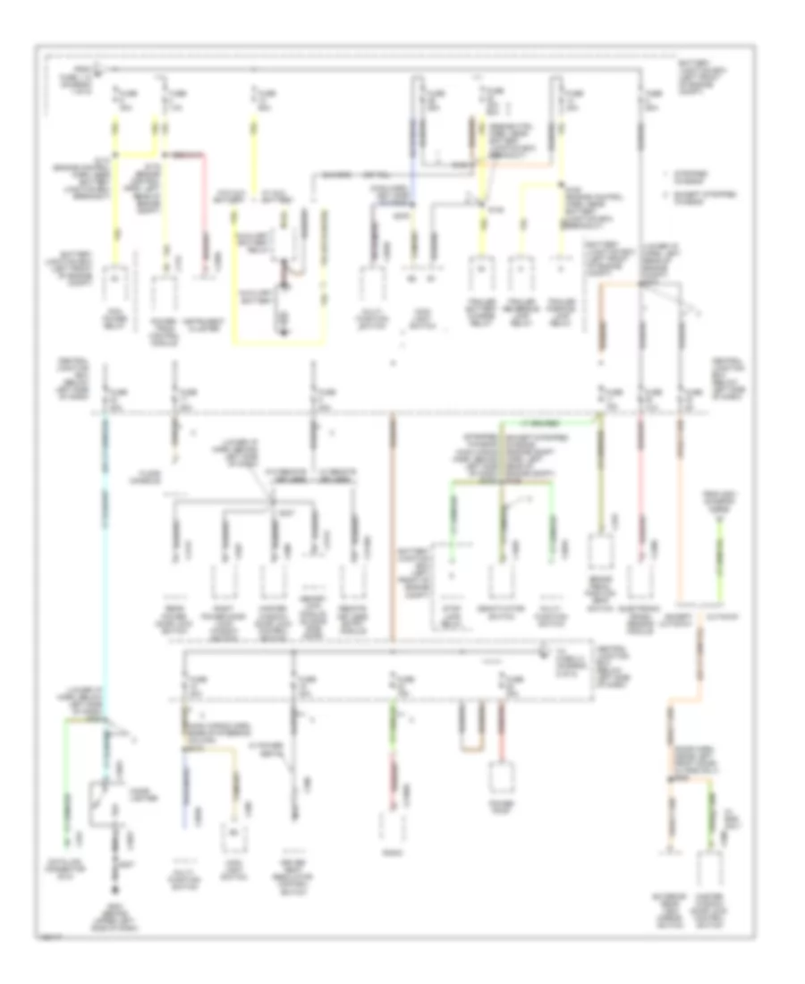
Power Distribution Wiring Diagram (1 of 5) for Ford Econoline E350 Super Duty 2002


List of elements for Power Distribution Wiring Diagram (1 of 5) for Ford Econoline E350 Super Duty 2002:
- (5.4l ngv only)
- (at breakout to glow plug relay) s191
- (diesel only)
- (e550)
- (engine control harn, near battery junction box breakout) s115
- (engine control harn, near battery junction box breakout) s116
- (engine harn, at breakout to glow plug module) s192
- (engine harn, at breakout to glow plug relay) s191
- (ex stripped chassis: lower i/p harn, left rear of engine compt) (stripped chassis: main harn, right side of steering column)
- (except e550)
- (lower i/p harn, near brake switch) s266
- (right front of engine compt, near starter motor relay)
- (taped in harness)
- A/c clutch relay
- Abs control module
- Auxiliary battery (diesel only)
- Battery (taped in harness)
- Battery feed (taped in harness)
- Battery junction box (left front of engine compt)
- Blower motor relay
- C135
- C152
- C153
- C155b
- C3140b
- California
- Central junction box (below left side of dash)
- Daytime running lamps module (if equipped)
- E550
- Electronic trailer brakes harness (taped in harness)
- Engine compartment battery
- Except california
- Except stripped chassis
- From a fuse 1.15 (diagram 1 of 5)
- Fuel pump relay
- Fuse
- Fuse 10a
- Fuse 15a
- Fuse 20a
- Fuse 30a
- Fuse 30a (diesel only)
- Fuse 40a
- Fuse 50a
- Fuse 60a
- Generator (gasoline) generator (primary) (diesel)
- Generator (secondary: diesel w/ twin generators)
- Glow plug control module
- Glow plug relay
- Horn relay
- Idm relay
- Main light switch
- Manifold intake air heater relay
- Modified vehicle power
- Nca
- Ngv module
- Power point (except cutaway)
- Power point console 1 (w/ rear seat entertainment system)
- Power point console 2 (w/ rear seat entertainment system)
- Rear a/c blower speed relay 1
- Red
- Remote keyless entry module
- S1008
- S101 (engine control harn, near battery junction box breakout)
- S1010 (right front of engine compt, near battery junction box)
- S1011 (right front of engine compt, near battery junction box)
- S1012 (right front of engine compt, near starter motor relay)
- S178 (right front of engine compt, near battery junction box)
- S183 (5.4l ngv only) (engine control harn, left rear of engine compt)
- S187 (engine harn, top right side of engine)
- S225 (except stripped chassis)
- S254 (lower i/p harn, near left kick panel)
- S257 (lower i/p harn, behind left 'b' pillar, near floor)
- S280 (stripped chassis)
- Starter motor
- Starter motor relay
- Stripped chassis
- To fuse 1.17 (diagram 1 of 5)
- To fuse 1.9 (diagram 2 of 5)
- To ignition switch (diagram 3 of 5)
- W/ remote keyless entry
- Wire ends in harness in cutaways
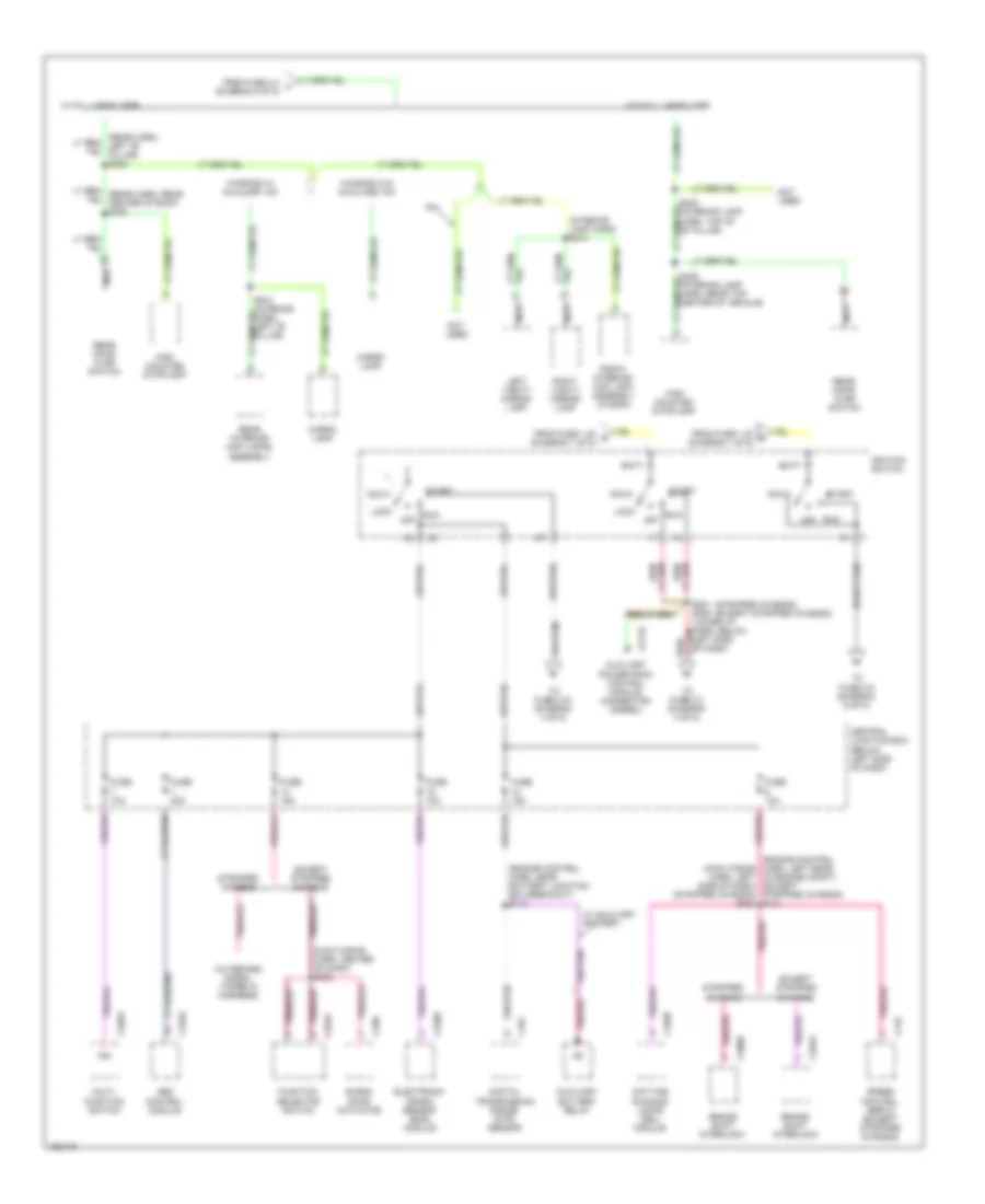
Power Distribution Wiring Diagram (2 of 5) for Ford Econoline E350 Super Duty 2002
List of elements for Power Distribution Wiring Diagram (2 of 5) for Ford Econoline E350 Super Duty 2002:
- (door harn, inside left front door) (w/ rke only) s506
- (engine ctrl harn, near battery junction box breakout)
- (lower i/p harn, behind left side of dash)
- (lower i/p harn, below left side of dash) s230
- (lower i/p harn, left rear of engine compt) s227
- (main harn, left side of dash)
- (main wiring harn, base of steering column) s218
- (stripped (except stripped chassis) (engine compt harn, left rear of engine compt) s129
- Auxiliary battery
- Auxiliary battery relay
- Battery junction box (left front of engine compt)
- Brake pedal position (bpp) switch
- C1025
- C175
- C202a
- C202b
- C2031
- C205
- C2188a
- C2209
- C220a
- C251
- C278
- C3131
- C3140a
- C360
- C4121
- C508
- C629
- Central junction box (below left side of dash)
- Chassis) (main wiring harn, behind left side of dash) s2020
- Cigar lighter
- Cutaway
- Data link connector (dlc)
- Deactivator switch
- Driver seat regulator control switch
- Electronic crash sensor module
- Except cutaway
- Except stripped chassis
- Exterior rear view mirror switch
- Floor console
- From b fuse 1.12 (diagram 1 of 5)
- From s221 (diagram 5 of 5)
- Fuse 10a
- Fuse 15a
- Fuse 20a
- Fuse 25a
- Fuse 30a
- Fuse 40a 60a
- Fuse 5a
- Fuse 60a
- G203 (behind upper left side of dash)
- Instrument cluster
- Main light switch
- Master window/ door lock control switch
- Memory lock module (sliding side door)
- Multi- function switch
- Nca
- Pcm power relay
- Power point
- Power- train control module
- Radio
- Rear power door lock switch
- Red
- Remote keyless entry nodule
- Right power door lock/ window switch
- S108
- S109 (engine control harn, near battery junction box breakout)
- S110 (engine control harn, near battery junction box breakout)
- S148
- S175 (engine control harn, left rear of engine compt)
- S207
- S237
- S276
- Stop lamp relay
- Stripped chassis
- To fuse 2.4 (diagram 5 of 5)
- Trailer battery charge relay
- Trailer parking lamp relay
- Trailer reversing lamp relay
- W/ aux battery
- W/ power seats
- W/ remote keyless
- W/ rke only
- W/o aux battery
- W/o remote keyless
Power Distribution Wiring Diagram (3 of 5) for Ford Econoline E350 Super Duty 2002
List of elements for Power Distribution Wiring Diagram (3 of 5) for Ford Econoline E350 Super Duty 2002:
- (engine control harn, left rear of engine compt) (except stripped chassis) s131
- (engine control harn, near battery junction box breakout) s113
- (interior lamp harn) s314
- (main wiring harn, center of dash) s203
- (main wiring harn, left side of dash) (stripped chassis) s282
- (stripped chassis) (except stripped chassis)
- A/c demand signal (taped in harness)
- Abs control module
- Acc
- Auxiliary battery relay
- Auxiliary powertrain control module connector (diesel)
- Batt
- Blend door actuator
- Brake shift interlock
- C1030
- C122
- C155a
- C167
- C2008
- C202a
- C2176
- C2209
- C289
- C294a
- Cargo lamp
- Central junction box (below left side of dash)
- Daytime running lamps (drl) module
- Digital transmission range (dtr) sensor
- Electronic crash sensor (ecs) module
- Except stripped chassis
- From fuse 1.23 c (diagram 1 of 5)
- From fuse 1.23 d (diagram 1 of 5)
- From fuse 2.4 j (diagram 5 of 5)
- Front interior/ map lamp assembly (wagon)
- Function selector switch
- Fuse 10a
- Fuse 15a
- Fuse 20a
- High mounted stoplamp
- Ign
- Ignition switch
- Left vanity mirror lamp
- Lock
- Multi- function switch
- Nca
- Not used
- Off
- R/v
- Rear door ajar switch
- Rear interior/ map lamps assembly
- Right vanity mirror lamp
- Run
- S281 s229 (lower i/p harn, below left side of dash)
- S302 (interior lamp harn, top of "b" pillar)
- S405 (interior lamp harn, rear top center of vehicle)
- S912 (interior harn, left "b" pillar)
- Speed control servo (except stripped chassis)
- Start
- Stripped chassis
- To fuse 2.2 (diagram 4 of 5)
- To fuse 2.34 (diagram 4 of 5)
- To fuse 2.9 (diagram 5 of 5)
- W/ auxiliary battery
- W/ full headliner
- W/o full headliner
- Wagons w/ auxiliary a/c
- Wagons w/o auxiliary a/c
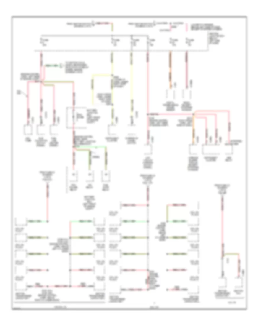
Power Distribution Wiring Diagram (4 of 5) for Ford Econoline E350 Super Duty 2002
List of elements for Power Distribution Wiring Diagram (4 of 5) for Ford Econoline E350 Super Duty 2002:
- (engine control harn, left rear of engine compt) s127
- (lower i/p harness, behind left side of dash) (except stripped chassis)
- (main wiring harn, under right side of dash) s267
- (other)
- (stripped)
- 4.2l v6
- 4.6l/5.4l v8
- 5.4l ngv
- 6.8l v10
- Abs relay
- Battery junction box (left front of engine compt)
- C1065
- C1076
- C1252
- C1254
- C167
- C174
- C2135
- C2156
- C2172
- C2188a
- C2206
- C220a
- C220c
- Central junction box (below left side of dash)
- Coil on plug 1
- Coil on plug 10
- Coil on plug 2
- Coil on plug 3
- Coil on plug 4
- Coil on plug 5
- Coil on plug 6
- Coil on plug 7
- Coil on plug 8
- Coil on plug 9
- Diesel
- Digital transmission range sensor
- From fuse 2.8 (diagram 4 of 5) (4.2l v6)
- From fuse 2.8 (diagram 4 of 5) (4.6l/5.4l)
- From fuse 2.8 (diagram 4 of 5) (6.8l v10)
- From ignition switch f (diagram 3 of 5)
- From ignition switch g (diagram 3 of 5)
- Fuel line heater (diesel)
- Fuel pump relay
- Fuse 10a
- Fuse 15a
- Fuse 30a
- Fuse 5a
- Idle validation switch (diesel)
- Idm relay
- Ignition coil
- Ignition transformer capacitor 1
- Ignition transformer capacitor 2
- Instrument cluster
- Low vacuum warning switch (diesel)
- Nca
- Ngv timer
- Overdrive cancel switch
- Pcm diode
- Pcm power relay
- Radio (except stripped chassis)
- S146 (engine control harn, left rear of engine compt)
- S156 (5.4l) s193 (4.6l) (engine control harn, above left cylinder bank)
- S161 (5.4l) s150 (4.6l) (engine control harn, above right cylinder bank)
- S161 (engine control harn, above right cylinder bank)
- S162 (engine control harn, above left cylinder bank)
- S213 (main wiring harn, left side of dash)
- S265 (lower i/p harn, under right side of dash)
- S269
- Tan/red
- To ignition coils (gasoline engines) or glow plug relay (diesel engine) (diagram 4 of 5)
- Warning buzzer module (except stripped chassis)
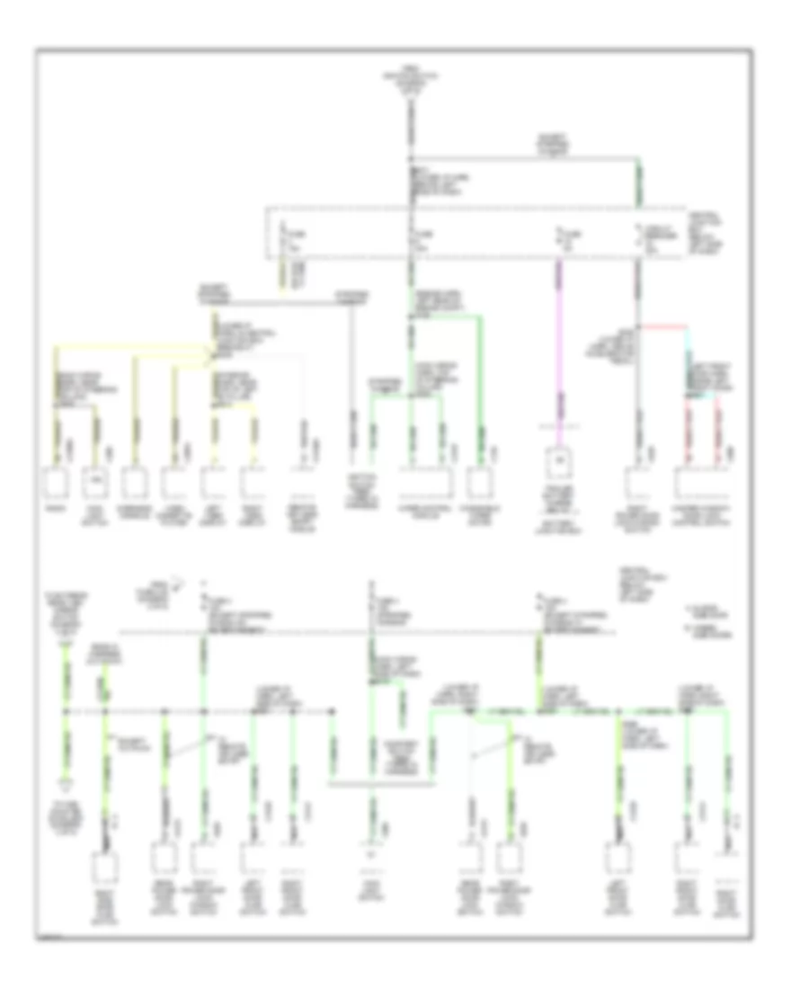
Power Distribution Wiring Diagram (5 of 5) for Ford Econoline E350 Super Duty 2002
List of elements for Power Distribution Wiring Diagram (5 of 5) for Ford Econoline E350 Super Duty 2002:
- (engine harn, left rear of engine compt) s128
- (left front door harn, inside left front door) s501
- (lower i/p harn, left side of dash) s221
- (lower i/p harn, left side of dash) s294
- (lower i/p harn, right side of dash) s221
- (main wiring harn, left side of dash) s219
- (main wiring harn, top of steering column) s208
- A sliding side door
- B hinged side doors
- Battery junction box
- C125
- C205
- C2157
- C2188a
- C3076
- C3129
- C3140a
- C3141
- C4121
- C508
- C629
- Central junction box (below left side of dash)
- Circuit breaker 20a
- Courtesy switch feed (taped in harness)
- Ends in harness (cutaway)
- Except cutaway
- Except stripped chassis
- From e fuse 2.28 (diagram 2 of 5)
- From ignition switch (diagram 3 of 5)
- Fuse 15a
- Fuse 30a
- Fuse 4 15a (except stripped chasis w/o entertainment)
- Fuse 4 15a (except stripped chassis w/ entertainment)
- Fuse 4 15a (stripped chassis)
- Fuse 5a
- Ign
- Ignition switch feed (taped in harness)
- Left front door ajar switch
- Left video display
- Main light switch
- Master window/ door lock control switch
- Nca
- Overhead console
- Radio
- Rear power door lock switch
- Remote keyless entry module
- Right door ajar switch
- Right front door ajar switch
- Right power door lock/ window switch
- Right power door lock/window switch
- Right side door ajar switch
- Right video display
- S236 (lower i/p harn, above accelerator pedal)
- S271 (lower i/p harn, behind left side of dash)
- S296 (lower i/p harn, left side of dash)
- Stripped chassis
- To exterior rear view mirror switch (diagram 2 of 5)
- To high mounted stoplamp (diagram 3 of 5)
- Trailer battery charge relay
- Video cassette player
- W/ remote keyless entry
- Windshield wiper motor
- Wiper control module

 Čeština
 Dansk
Dansk Deutsch
 Ελληνικά
 English
 English
 Español
 Suomi
Suomi Français
 Français
 עברית
עברית Hrvatski
 Magyar
 Italiano
 日本語
日本語 한국어
한국어 Nederlands
 Polski
 Português
 Português
 Română
 Русский
 Slovenčina
 Slovenščina
 Svenska
 中文 (中国)