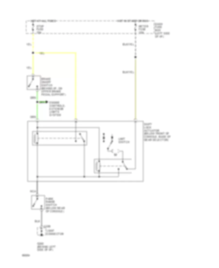
SHIFT INTERLOCKS
Shift Interlock Wiring Diagram for Ford Aspire 1994
 https://portal-diagnostov.com/license.html
Automotive Electricians Portal FZCO
Automotive Electricians Portal FZCO
https://portal-diagnostov.com/license.html
https://portal-diagnostov.com/license.html
Automotive Electricians Portal FZCO
Automotive Electricians Portal FZCO
List of elements for Shift Interlock Wiring Diagram for Ford Aspire 1994:
- Brake on/off switch (behind i/p, on upper brake pedal support)
- C206
- Dash fuse box (left side of i/p)
- Engine controls, exterior lights system
- G202 (behind left side of i/p)
- Hot at all times
- Hot in start or run
- Joint connector
- Limit switch
- Meter fuse 15a
- Nca
- Park range switch (below rear of console)
- Shift lock actuator (below front of console, base of gear selector)
- Stop fuse 15a
 Čeština
 Dansk
Dansk Deutsch
 Ελληνικά
 English
 English
 Español
 Suomi
Suomi Français
 Français
 עברית
עברית Hrvatski
 Magyar
 Italiano
 日本語
日本語 한국어
한국어 Nederlands
 Polski
 Português
 Português
 Română
 Русский
 Slovenčina
 Slovenščina
 Svenska
 中文 (中国)
 Türkçe
