AIR CONDITIONING
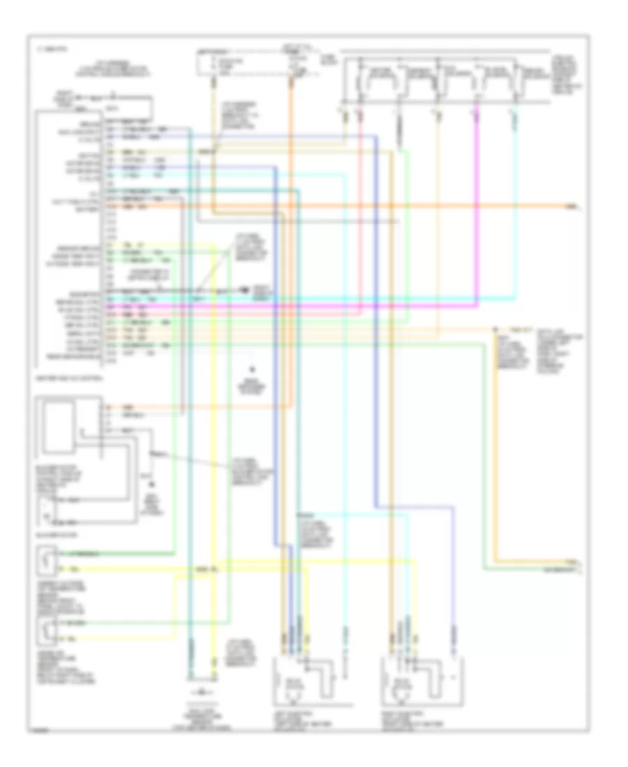
A/C Wiring Diagram, Auto A/C (1 of 2) for Pontiac Grand Prix GTP 1998
 https://portal-diagnostov.com/license.html
Automotive Electricians Portal FZCO
Automotive Electricians Portal FZCO
https://portal-diagnostov.com/license.html
https://portal-diagnostov.com/license.html
Automotive Electricians Portal FZCO
Automotive Electricians Portal FZCO
List of elements for A/C Wiring Diagram, Auto A/C (1 of 2) for Pontiac Grand Prix GTP 1998:
- (i/p harn, 4 cm from blower motor control mod breakout)
- (i/p harn, 11 cm from data link connector breakout)
- (i/p harn, 37 cm from data link connector breakout)
- (i/p harn, 43 cm from data link connector breakout)
- (i/p harness, 4 cm from blower motor control module breakout)
- (i/p harness, 4 cm from breakout to data link connector)
- (right side of dash)
- (right side of dash) g201
- +5 v
- 5 volts
- A/c request
- A/c sol ctrl
- A/c solenoid
- Ambient outside air temperature sensor (behind front panel, mount to radiator baffle)
- Battery
- Bi-lev sol ctrl
- Bi-level solenoid
- Blower motor
- Blower motor control module (in right side of heater-a/c module)
- C 1995 vftc
- C10
- C11
- C12
- C13
- C14
- C15
- C16
- Connected w/ metric display
- D10
- D11
- D12
- D13
- D14
- D15
- D16
- Data link (dlc) connector (under left side of dash, right side of steering column)
- Def sol ctrl
- Defrost solenoid
- Dic/hvac fuse 10a
- Eng/metric
- Fuse block
- G201
- G201 (right side of dash)
- Ground
- Heater and a/c control
- Heater solenoid
- Hot at all times
- Hot in run
- Htr sol ctrl
- Hvac hi fuse 30a
- Ignition
- Inside air temperature sensor (front of dash, below right side of instrument cluster)
- Inside temp input
- Left electric actuator (left side of heater- a/c module)
- Motor drive
- Nca
- Outside temp input
- Rear defog enable
- Rear defogger system
- Recirc sol ctrl
- Recirc solenoid
- Red
- Right electric actuator (right side of heater- a/c module)
- S206
- S211
- S213
- S237 (i/p harn, 30 cm from data link connector breakout)
- S245
- S258
- Sensor ground
- Serial data
- Solid state
- Sun load input
- Sun load temperature sensor (top center of dash)
- Tan
- Vacuum/ electric solenoid (on right side of heater-a/c module)
- Volt to blw ctrl
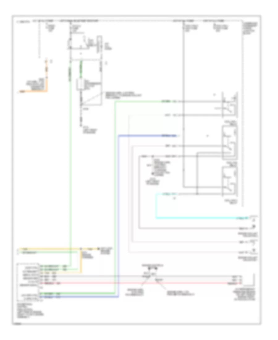
A/C Wiring Diagram, Auto A/C (2 of 2) for Pontiac Grand Prix GTP 1998
 https://portal-diagnostov.com/license.html
Automotive Electricians Portal FZCO
Automotive Electricians Portal FZCO
https://portal-diagnostov.com/license.html
https://portal-diagnostov.com/license.html
Automotive Electricians Portal FZCO
Automotive Electricians Portal FZCOList of elements for A/C Wiring Diagram, Auto A/C (2 of 2) for Pontiac Grand Prix GTP 1998:
- (engine harn, 15 cm from pcm breakout)
- (engine harn, 4 cm from breakout to engine coolant fan jumper)
- (engine harn, 7 cm from ebtcm breakout)
- 5 volts
- A/c clu diode
- A/c clu fuse 10a
- A/c clu relay
- A/c compressor clutch coil
- A/c refrigerant pressure sensor (on left side of engine compt, on accumulator)
- A/c request
- A10
- Anti-lock brakes system
- C 1995 vftc
- C10
- C11
- Comp ctrl
- Cool fan 1 maxi fuse 30a
- Cool fan 1 relay
- Cool fan 2 maxi fuse 30a
- Cool fan 2 relay
- Cool fan relay
- Engine controls system
- Engine coolant fan motor 1
- Engine coolant fan motor 2
- F11
- G110 (left front of engine)
- Hi spd ctrl
- Hot at all times
- Hot in run, bulb test or start
- Low spd ctrl
- Powertrain control module (pcm) (left side of engine compt, in air cleaner assembly)
- Radio fuse 10a
- S105
- S105 (engine harn, 4 cm from breakout to engine coolant fan jumper)
- S122
- S131 (engine harness)
- S167
- S202 (i/p harn, 17 cm from data link connector breakout)
- Sensor grd
- Sensor signal
- Serial data
- Tan
- Underhood accessory wiring junction block
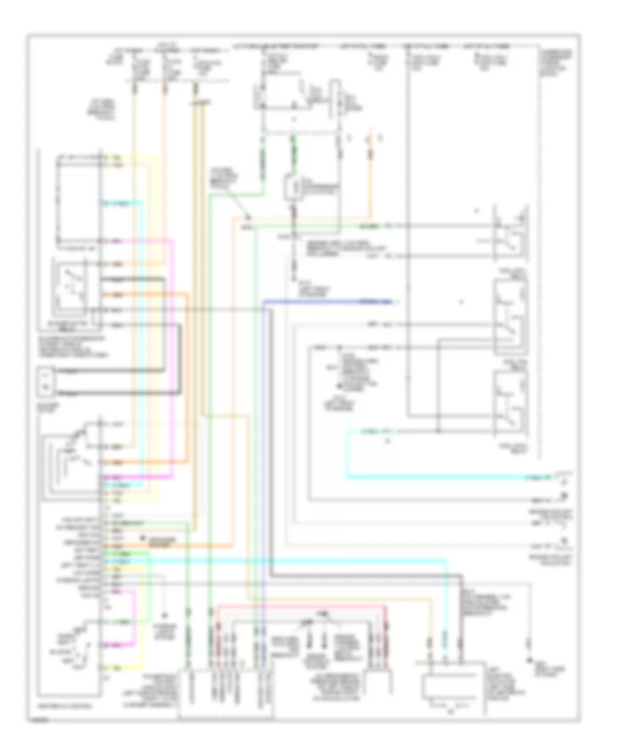
A/C Wiring Diagram, Manual A/C for Pontiac Grand Prix GTP 1998
 https://portal-diagnostov.com/license.html
Automotive Electricians Portal FZCO
Automotive Electricians Portal FZCO
https://portal-diagnostov.com/license.html
https://portal-diagnostov.com/license.html
Automotive Electricians Portal FZCO
Automotive Electricians Portal FZCOList of elements for A/C Wiring Diagram, Manual A/C for Pontiac Grand Prix GTP 1998:
- (eng harn, 15 cm from pcm breakout)
- (engine harn, 4 cm from breakout to engine coolant fan jumper)
- (engine harness, 7 cm from ebtcm breakout)
- (i/p harn, 17 cm from breakout to dlc)
- (i/p harn, 4 cm from breakout to dlc)
- 5 volts
- A nca
- A/c clu diode
- A/c clu relay
- A/c clu/ abs ign fuse 10a
- A/c compressor clutch coil
- A/c refrigerant pressure sensor (on left side of engine compt, on accumulator)
- A/c request sig
- A10
- Battery
- Bi-level
- Blend
- Blower motor
- Blower motor relay
- Blower motor resistor (in right side of heater-a/c module, under right side of dash)
- C10
- C11
- Clutch req
- Comp ctrl
- Cool fan 1 maxi fuse 30a
- Cool fan 1 relay
- Cool fan 2 maxi fuse 30a
- Cool fan 2 relay
- Cool fan relay
- Def
- Def mode
- Defogger on
- Defogger system
- Dic/hvac fuse 10a
- Engine controls system
- Engine coolant fan motor 1
- Engine coolant fan motor 2
- F11
- Fan off input
- Fan on
- Fuse block
- G110 (left front of engine)
- G201 (right side of dash)
- Ground
- Heat
- Heater-a/c control
- Hi spd ctrl
- Hot at all times
- Hot in run
- Hot in run, bulb test or start
- Hvac ctrl fuse 20a
- Hvac hi fuse 30a
- Ignition
- Interior lights
- Interior lights system
- Left electric actuator (left side of heater-a/c module)
- Left temp vlv
- Low spd ctrl
- Max
- Max mode
- Nca
- Off
- Powertrain control module (pcm) (left side of engine compt, in air cleaner assembly)
- Radio fuse 10a
- S105
- S105 (engine harn, 4cm from breakout to engine coolant fan jumper)
- S122
- S167
- S202
- S206
- S213 (i/p harness, 4 cm from blower motor resistor breakout)
- Sensor grd
- Sensor sig
- Tan
- Underhood accessory wiring junction block
- Vent
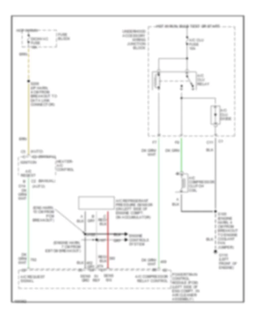
Compressor Wiring Diagram for Pontiac Grand Prix GTP 1998
 https://portal-diagnostov.com/license.html
Automotive Electricians Portal FZCO
Automotive Electricians Portal FZCO
https://portal-diagnostov.com/license.html
https://portal-diagnostov.com/license.html
Automotive Electricians Portal FZCO
Automotive Electricians Portal FZCOList of elements for Compressor Wiring Diagram for Pontiac Grand Prix GTP 1998:
- (auto)
- (eng harn, 15 cm from pcm breakout)
- (engine harn, 7 cm from ebtcm breakout)
- (manual) c2
- 5v ref
- A/c clu diode
- A/c clu fuse 10a
- A/c clu relay
- A/c compressor clutch coil
- A/c compressor relay control
- A/c refrigerant pressure sensor (on left side of engine compt, on accumulator)
- A/c reqest
- A/c request signal
- C11
- Dic/hvac fuse 10a
- Engine controls system
- Fan jumper)
- Fuse block
- G110 (left front of engine)
- Heater- a/c control
- Hot in run
- Hot in run, bulb test or start
- Ignition
- Powertrain control module (pcm) (left side of eng compt, in air cleaner assembly)
- S122
- S167
- S206 (i/p harn, 4 cm from breakout to data link connector)
- Sens grd
- Sens sig
- Underhood accessory wiring junction block

 Čeština
 Dansk
Dansk Deutsch
 Ελληνικά
 English
 English
 Español
 Suomi
Suomi Français
 Français
 עברית
עברית Hrvatski
 Magyar
 Italiano
 日本語
日本語 한국어
한국어 Nederlands
 Polski
 Português
 Português
 Română
 Русский
 Slovenčina
 Slovenščina
 Svenska
 中文 (中国)
