ENGINE PERFORMANCE
4.0L
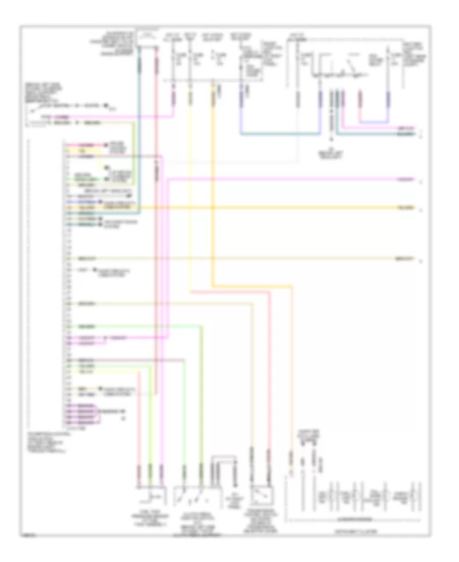
4.0L, Engine Performance Wiring Diagram (1 of 4) for Mazda B4000 2008
 https://portal-diagnostov.com/license.html
Automotive Electricians Portal FZCO
Automotive Electricians Portal FZCO
https://portal-diagnostov.com/license.html
https://portal-diagnostov.com/license.html
Automotive Electricians Portal FZCO
Automotive Electricians Portal FZCO
List of elements for 4.0L, Engine Performance Wiring Diagram (1 of 4) for Mazda B4000 2008:
- (behind left headlight) g6
- (behind left side of dash, on brake pedal support) brake pedal position switch
- 0140-175b
- 0922-101
- Air conditioning system
- Battery junction box (left rear of engine compt)
- Check engine ind
- Clutch pedal position switch (m/t) (behind left side of dash, top of clutch pedal support)
- Computer data lines system
- Cruise control system
- Evaporative emission (evap) canister vent valve (under vehicle, on frame cross support)
- Fail- safe cooling ind
- Fuel cap ind
- Fuel tank pressure sensor (at fuel tank assembly)
- Fuse 10a
- Fuse 30a
- Fuse 5a
- G11 (at right kick panel)
- G13
- G4 (behind left headlight)
- Hot at all times
- Hot in run
- Hot in run or start
- Instrument cluster
- J-2280a
- J-2280b
- Microprocessor
- Nca
- O/d off ind
- Pcm power diode
- Pcm power relay
- Powertrain control module (pcm) (at right rear of engine compt, through firewall)
- Ptc circuit breaker 1a
- Smart junction box (at right kick panel)
- Starting/ charging system
- Transmission control switch (od on/off) (on end of transmission selector lever)
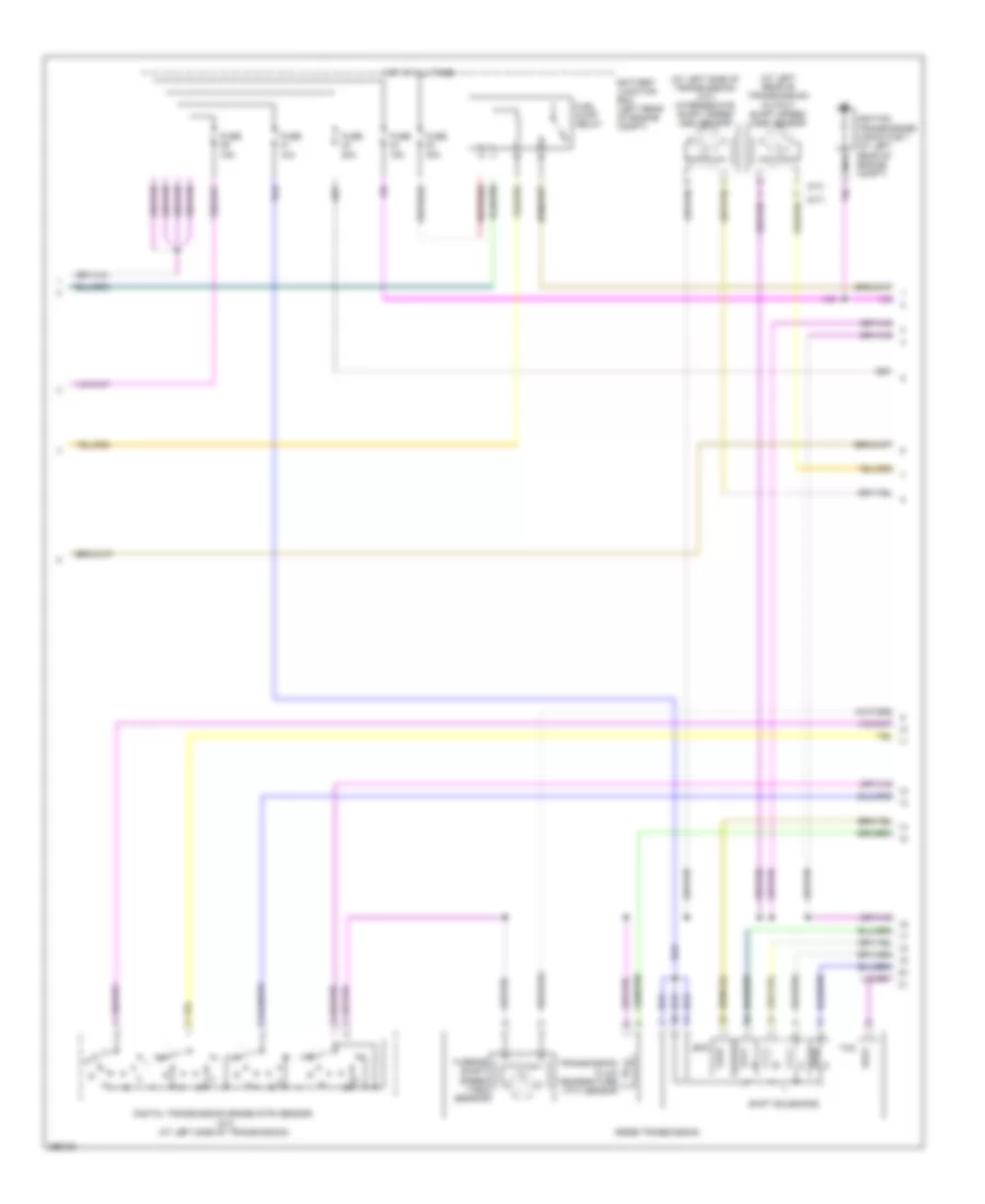
4.0L, Engine Performance Wiring Diagram (2 of 4) for Mazda B4000 2008
 https://portal-diagnostov.com/license.html
Automotive Electricians Portal FZCO
Automotive Electricians Portal FZCO
https://portal-diagnostov.com/license.html
https://portal-diagnostov.com/license.html
Automotive Electricians Portal FZCO
Automotive Electricians Portal FZCOList of elements for 4.0L, Engine Performance Wiring Diagram (2 of 4) for Mazda B4000 2008:
- (a/t)
- (at left rear of transmission) output shaft speed (oss) sensor
- (at left side of transmission) (a/t) intermediate shaft speed (iss) sensor
- (m/t)
- 5r55e transmission
- Battery junction box (left rear of engine compt)
- Digital transmission range (dtr) sensor (a/t) (at left side of transmission)
- Epc
- Fuel pump relay
- Fuse 10a
- Fuse 15a
- Fuse 20a
- Fuse 30a
- Hot at all times
- Ignition transformer capacitor 1 (at left rear of engine compt)
- Nca
- Shift solenoids
- Tcc
- Transmission fluid temperature (tft) sensor
- Turbine shaft speed (tss) sensor
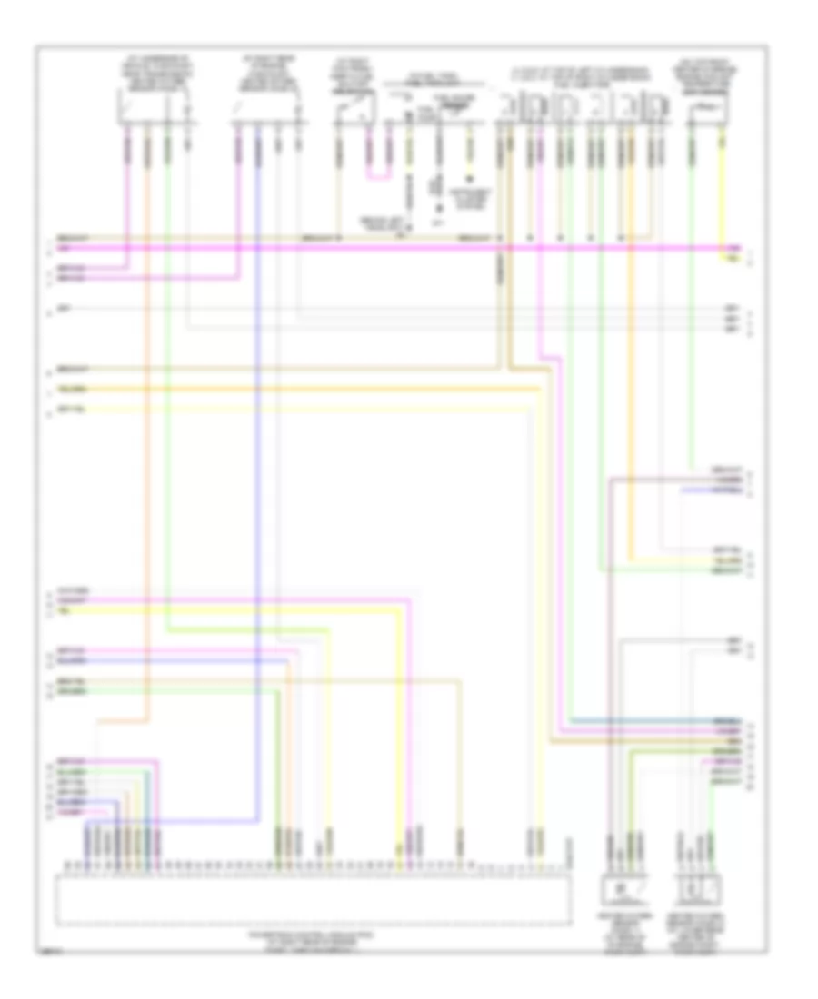
4.0L, Engine Performance Wiring Diagram (3 of 4) for Mazda B4000 2008
 https://portal-diagnostov.com/license.html
Automotive Electricians Portal FZCO
Automotive Electricians Portal FZCO
https://portal-diagnostov.com/license.html
https://portal-diagnostov.com/license.html
Automotive Electricians Portal FZCO
Automotive Electricians Portal FZCOList of elements for 4.0L, Engine Performance Wiring Diagram (3 of 4) for Mazda B4000 2008:
- (4, 5 & 6: at top of left cylinder bank) (1, 2 & 3: at top of right cylinder bank) fuel injectors
- (at right kick panel) inertia fuel shutoff (ifs) switch
- (at right rear of engine, in exhaust) heated oxygen sensor (ho2s) 22
- (at underside of vehicle, in exhaust, near transmission) heated oxygen sensor (ho2s) 12
- (behind left headlight) g4
- (in fuel tank) fuel tank unit
- (on top front center of engine) engine coolant temperature (ect) sensor
- 0140-175t
- Fuel gauge sensor
- Fuel pump
- G11
- Heated oxygen sensor (ho2s) 11 (at rear of of engine, in exhaust)
- Heated oxygen sensor (ho2s) 21 (at lower rear center of engine compt, in exhaust)
- Instrument cluster system
- Powertrain control module (pcm) (at right rear of engine compt, through firewall)
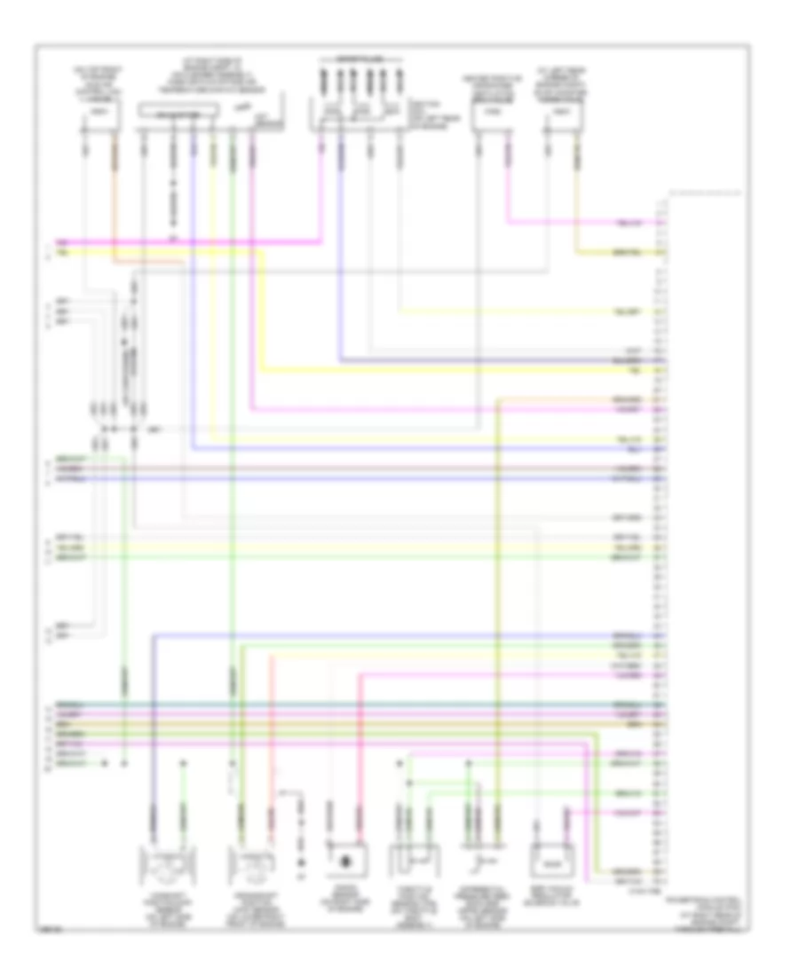
4.0L, Engine Performance Wiring Diagram (4 of 4) for Mazda B4000 2008
 https://portal-diagnostov.com/license.html
Automotive Electricians Portal FZCO
Automotive Electricians Portal FZCO
https://portal-diagnostov.com/license.html
https://portal-diagnostov.com/license.html
Automotive Electricians Portal FZCO
Automotive Electricians Portal FZCOList of elements for 4.0L, Engine Performance Wiring Diagram (4 of 4) for Mazda B4000 2008:
- (at left rear corner of engine compt) evap canister purge valve
- (at right side of engine compt, in air cleaner assembly) mass air flow/intake air temperature (maf/iat) sensor
- (on top front of engine) idle air control (iac) valve
- 0140-175e
- Act sensor
- Air conditioning system
- Camshaft position (cmp) sensor (on left side of engine)
- Crankshaft position (ckp) sensor (on lower right front of engine)
- Differential pressure feed- back egr (dpfe) sensor (on left side of engine)
- Egr vacuum regulator solenoid valve
- Heated positive crankcase ventilation (pcv) valve
- Ignition coil (on left rear of engine)
- Knock sensor (on right side of engine)
- Nca
- Powertrain control module (pcm) (at right rear of engine compt, through firewall)
- Solid state
- Spark plugs
- Throttle position sensor (tps) (on throttle body assembly)

 Čeština
 Dansk
Dansk Deutsch
 Ελληνικά
 English
 English
 Español
 Suomi
Suomi Français
 Français
 עברית
עברית Hrvatski
 Magyar
 Italiano
 日本語
日本語 한국어
한국어 Nederlands
 Polski
 Português
 Português
 Română
 Русский
 Slovenčina
 Slovenščina
 Svenska
 中文 (中国)
