AIR CONDITIONING
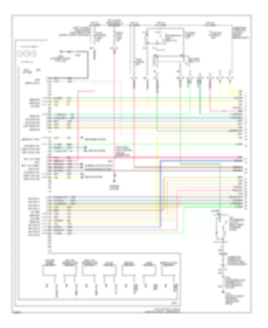
Automatic A/C Wiring Diagram (1 of 2) for Chevrolet Corvette 2006
 https://portal-diagnostov.com/license.html
Automotive Electricians Portal FZCO
Automotive Electricians Portal FZCO
https://portal-diagnostov.com/license.html
https://portal-diagnostov.com/license.html
Automotive Electricians Portal FZCO
Automotive Electricians Portal FZCO
List of elements for Automatic A/C Wiring Diagram (1 of 2) for Chevrolet Corvette 2006:
- (39 cm from hvac control
- A/c comp fuse 15 10a
- A/c comp relay 35
- A/c compressor clutch (right front of engine block)
- A/c off switch
- Bat
- Blower ctrl
- Blower speed switch
- Body control module (bcm) (mounted on toe board, in right footwell)
- C1 c10
- C4 d8 pnk
- Coolfan fuse 25 60a
- Defog rly ctrl
- Defogger system
- Defrost frost
- Defrost switch
- Dr ctrl a
- Dr ctrl b
- Drv htd st sig
- E1 c2
- F13
- F14
- G102 (on top of right frame rail, ground for sp102)
- G202 (at base of right "a" pillar)
- Gnd
- H13
- H14
- Hot at all times
- Hot w/ run/ crank relay 2 energized
- Hvac control module (center of dash, under radio)
- Hvac fuse 28 40a
- Hvac/ pwr snd fuse 10a
- Ign
- Ign 1 voltage
- Interior lights system
- Isrvm/ hvac fuse 10a
- Lamp ctrl
- Left air temperature switch
- Light sens sig
- Logic
- Low ref
- Mirrors system
- Mode ctrl
- Mode switch
- Module connector)
- Mtr spd ctrl
- Off ctrl
- Pass htd st sig
- Pnk
- Powertrain ign 1 relay 44
- Recirc ctrl
- Recirculation switch
- Red
- Right air temperature switch
- S216
- S231
- Seats system
- Sens sig
- Serial data
- Speed ctrl
- Sply voltage
- Sply voltage 4
- Sunload sig
- Tan
- Temp ctrl
- Temp ctrl sig
- To c120)
- Transmissions system
- Underhood fuse block (on right side of engine compt)
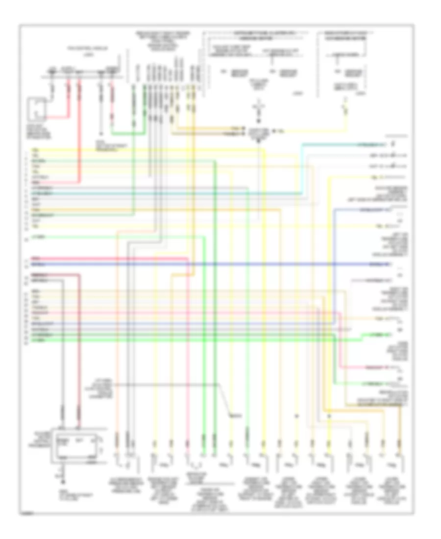
Automatic A/C Wiring Diagram (2 of 2) for Chevrolet Corvette 2006
 https://portal-diagnostov.com/license.html
Automotive Electricians Portal FZCO
Automotive Electricians Portal FZCO
https://portal-diagnostov.com/license.html
https://portal-diagnostov.com/license.html
Automotive Electricians Portal FZCO
Automotive Electricians Portal FZCOList of elements for Automatic A/C Wiring Diagram (2 of 2) for Chevrolet Corvette 2006:
- (behind right front fender, between wheelhouse & dash panel) engine control module (ecm)
- (i/p harn, 35 cm from hvac control module connector)
- 5v ref
- A/c refrigerant pressure sensor (on a/c high pressure line)
- Ambient air temperature sensor (on radiator support, at right front of engine)
- Aspirator blower motor
- Bat
- Blower motor control processor
- Check gages
- Computer data lines system
- Coolant fan motor (behind side of radiator)
- Coolant over temp engine hot/stop engine low coolant
- Engine coolant temperature (ect) sensor (in front lift side of left cylinder head)
- Fan control module
- G102 (on top of right frame rail)
- G202 (at base of right "a" pillar)
- Gnd
- Head up display (hud)
- Hot engine-a/c off service a/c
- Hud class 2 serial data
- Hud message center
- Ign
- Ignition 1
- Inside air temperature sensor (right side of steering column, in air outlet vent)
- Instrument panel cluster (ipc)
- Ipc class 2 serial data
- Left air temperature actuator (on left side of hvac module assembly)
- Logic
- Low ref
- Low ref c2 tan
- Lower left air temperature sensor (in left middle of hvac module)
- Lower right air temperature sensor (in right middle of hvac module)
- Message center
- Message request
- Mode actuator (right side of hvac module)
- Pnk
- Recirculation actuator (mounted to right side of blower motor assembly)
- Red
- Right air temperature actuator (on right side of hvac module assembly)
- Rly ctrl
- S242
- Sens sig
- Serial data +
- Serial data - c1 tan
- Spd ctrl
- Speed ctrl
- Sunload sensor assembly (on top of dash, left side of defroster grille)
- Tan
- Upper left air temperature sensor (in left center of dash, in hvac air flow duct)
- Upper right air temperature sensor (in upper right of dash, in hvac air flow duct)
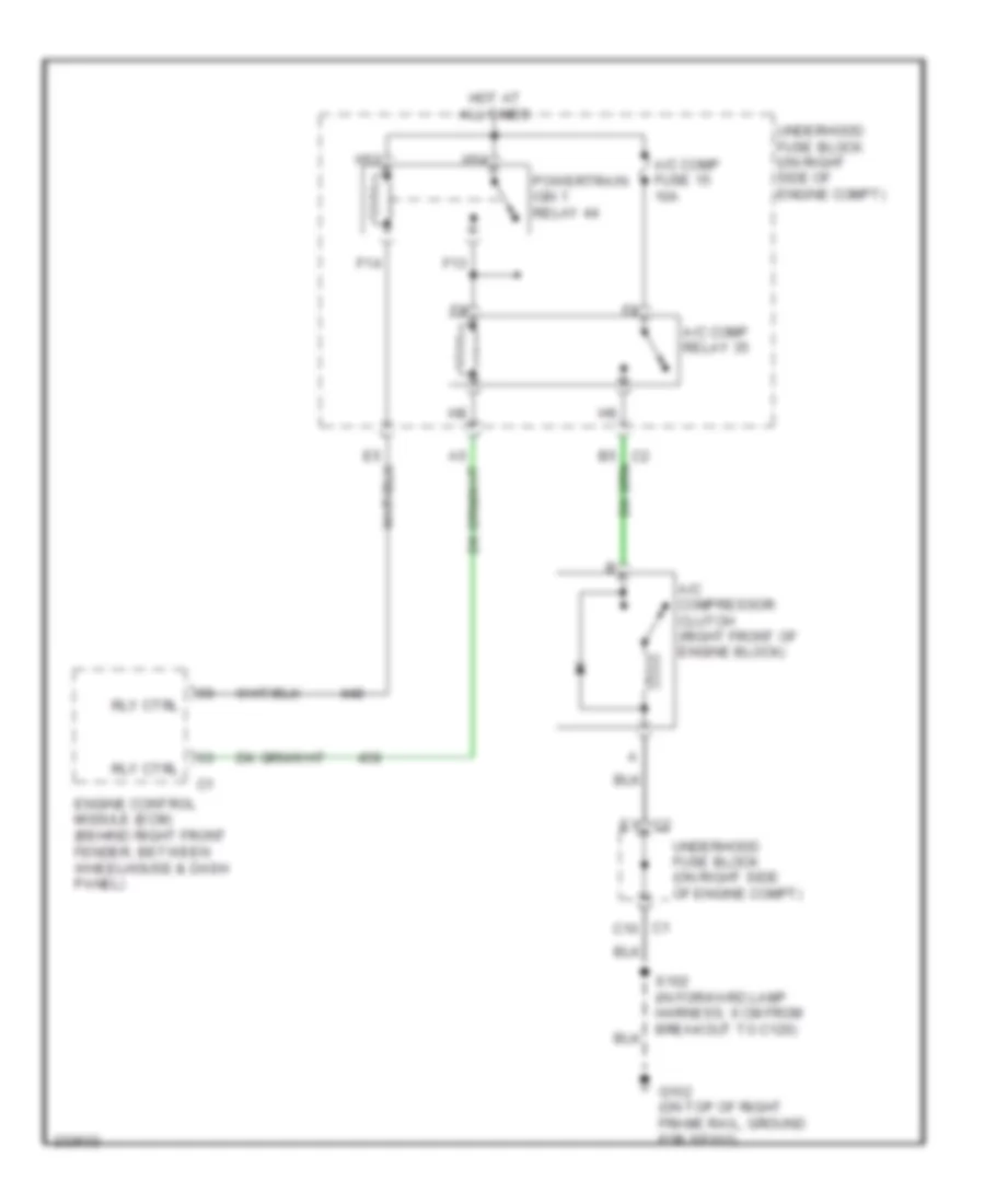
Compressor Wiring Diagram for Chevrolet Corvette 2006
 https://portal-diagnostov.com/license.html
Automotive Electricians Portal FZCO
Automotive Electricians Portal FZCO
https://portal-diagnostov.com/license.html
https://portal-diagnostov.com/license.html
Automotive Electricians Portal FZCO
Automotive Electricians Portal FZCOList of elements for Compressor Wiring Diagram for Chevrolet Corvette 2006:
- A/c comp fuse 15 10a
- A/c comp relay 35
- A/c compressor clutch (right front of engine block)
- C1 c10
- E1 c2
- Engine control module (ecm) (behind right front fender, between wheelhouse & dash panel)
- F13
- F14
- G102 (on top of right frame rail, ground for sp102)
- H13
- H14
- Hot at all times
- Powertrain ign 1 relay 44
- Rly ctrl
- Underhood fuse block (on right side of engine compt)

 Čeština
 Dansk
Dansk Deutsch
 Ελληνικά
 English
 English
 Español
 Suomi
Suomi Français
 Français
 עברית
עברית Hrvatski
 Magyar
 Italiano
 日本語
日本語 한국어
한국어 Nederlands
 Polski
 Português
 Português
 Română
 Русский
 Slovenčina
 Slovenščina
 Svenska
 中文 (中国)
