AIR CONDITIONING
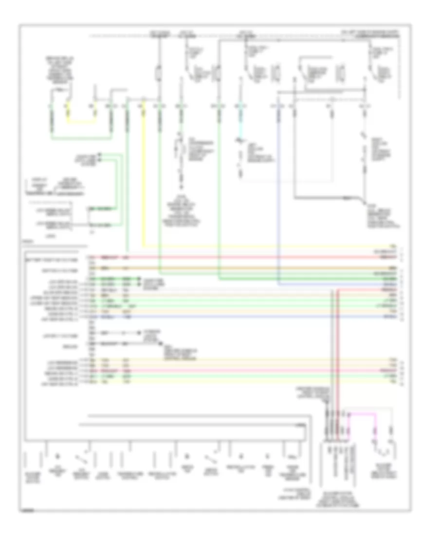
Automatic A/C Wiring Diagram (1 of 2) for Chevrolet Malibu LS 2007
 https://portal-diagnostov.com/license.html
Automotive Electricians Portal FZCO
Automotive Electricians Portal FZCO
https://portal-diagnostov.com/license.html
https://portal-diagnostov.com/license.html
Automotive Electricians Portal FZCO
Automotive Electricians Portal FZCO
List of elements for Automatic A/C Wiring Diagram (1 of 2) for Chevrolet Malibu LS 2007:
- (behind grille, on left side of front impact bar) ambient air temperature sensor
- (center console, front of body control module) g203
- (on left side of engine compt) underhood fuse block
- A/c clu fuse 1 10a
- A/c clutch relay
- A/c compressor clutch (lower right front of engine)
- A/c request ind
- A/c request switch
- A10
- A11
- A11 c2
- A12
- A2 c1
- Air temp dr ctrl a
- Air temp dr ctrl b
- Ambient air temperature
- B10
- B10 c2
- B11
- B12
- B9 c3
- Bat
- Battery positive voltage
- Blower motor (below right side of dash)
- Blower motor control module (right side of dash, on rear of hvac case)
- Blower motor switch
- Blr mtr spd ctrl
- Blr spd req sig
- Blwr spd req sig
- C1 e3
- Computer data lines system
- Cool fan 1 fuse 17 30a
- Cool fan 2 fuse 18 30a
- Cool/ fan 1 relay
- Cool/ fan 2 relay
- Cool/fan ser/par relay
- Defog ind
- Defog switch
- Display
- Driver information display
- E1 c2
- E8 c1
- Fresh air ind
- G106 (2.2l: below generator) (3.5l: near park/neutral position switch)
- G106 (2.2l: on engine, below generator) (3.5l: on transmission, near park/neutral position switch)
- G201 (center console, front of body control module)
- Gnd
- Ground
- Hot at all times
- Hot in run or start
- Hvac control module (center of dash)
- Ignition 3 voltage
- Inside air temperature sensor
- Interior lights system
- Left cooling fan (on front of engine compt)
- Lmp sply voltage
- Logic
- Low coolant
- Low reference
- Low spd gmlan
- Low speed gmlan serial data
- Lower air temp sens sig
- Mode dr ctrl a
- Mode dr ctrl b
- Mode switch
- Radio
- Recirc dr ctrl a
- Recirc dr ctrl b
- Recirculation ind
- Recirculation switch
- Right cooling fan (on front of engine compt)
- Sply voltage
- Tan
- Temperature control
- Upper air temp sens sig
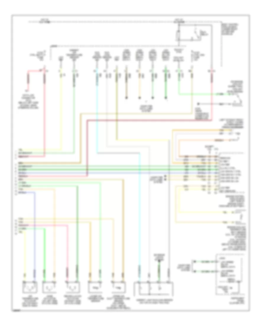
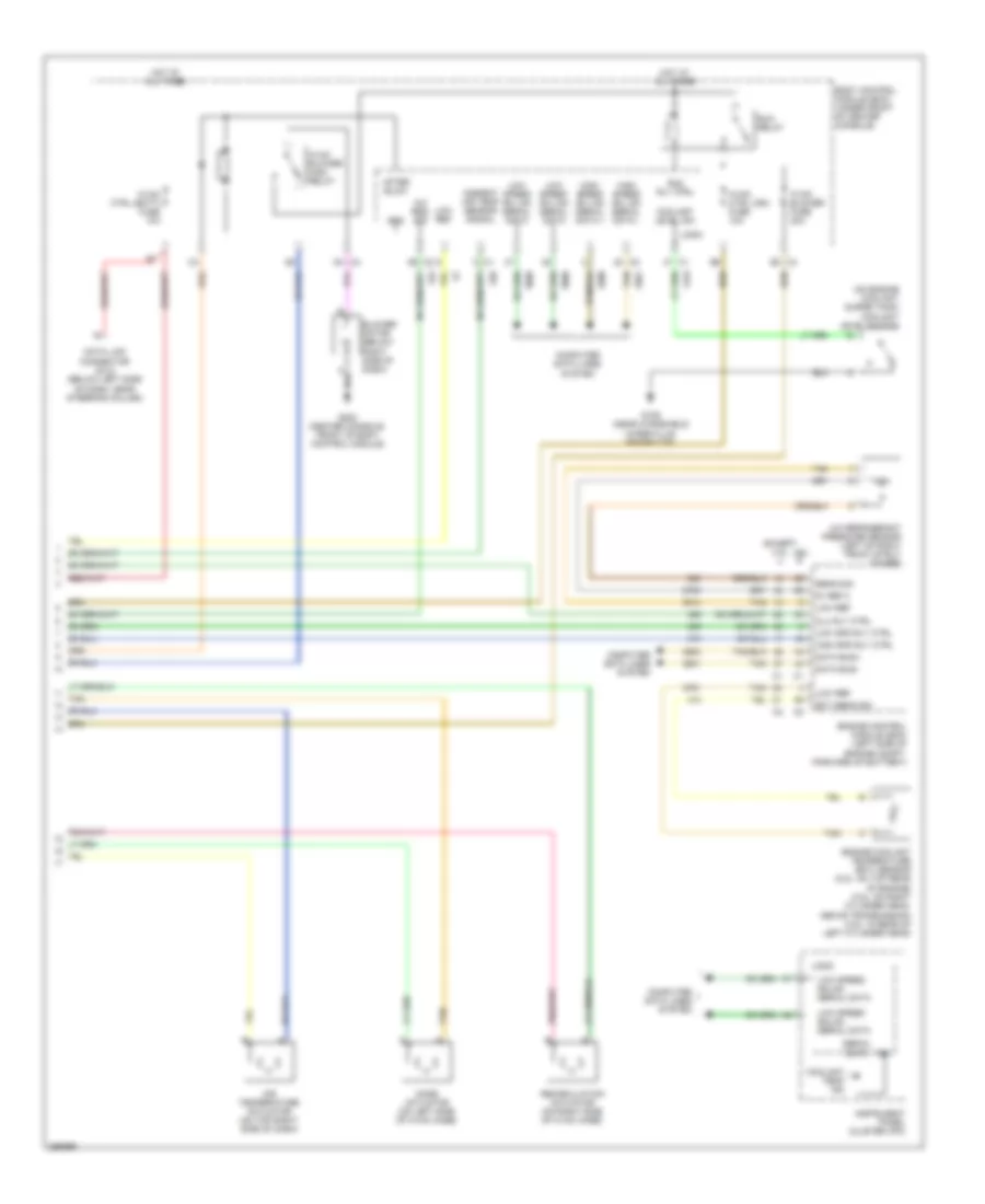
Automatic A/C Wiring Diagram (2 of 2) for Chevrolet Malibu LS 2007
 https://portal-diagnostov.com/license.html
Automotive Electricians Portal FZCO
Automotive Electricians Portal FZCO
https://portal-diagnostov.com/license.html
https://portal-diagnostov.com/license.html
Automotive Electricians Portal FZCO
Automotive Electricians Portal FZCOList of elements for Automatic A/C Wiring Diagram (2 of 2) for Chevrolet Malibu LS 2007:
- (left of right front strut tower) a/c refrigerant pressure sensor
- (on engine coolant surge tank) coolant level switch
- 2.2l
- 5v ref 1
- Air temperature actuator (on top right side of dash)
- Ambient air temperature sensor sig
- Ambient light/sunload sensor (on top of dash trim pad)
- Body control module (bcm) (under front of center console)
- C4 e2
- Clu rly ctrl
- Computer data lines system
- Coolant level sw
- Coolant temp ind
- Data link connector (dlc) (below left side of dash, near steering column)
- Ect sens sig
- Engine control module (ecm) (left side of engine compt, forward of battery)
- Engine coolant temperature (ect) sensor (2.2l: on top rear of engine (3.5l: on right cylinder head, above transmission) (3.9l: in rear of left cylinder head)
- Except 2.2l
- Exterior lights system
- G109 (near windshield wiper fluid reservoir)
- High spd gm lan
- High spd rly ctrl
- High speed gm lan serial data +
- High speed gm lan serial data -
- Hot at all times
- Hvac ctrl (batt) fuse 10a
- Hvac ctrl (ign) fuse 10a
- Ign
- Instrument panel cluster (ipc)
- Logic
- Low ref
- Low spd rly ctrl
- Low speed gm lan serial data
- Low speed gmlan serial data
- Lower air temperature sensor
- Mode actuator (on left side of hvac case)
- Recirculation actuator (on right side of hvac case)
- Run relay
- Run rly ctrl
- Sens sig
- Serial data
- Sun load sensor sig
- Tan
- Upper air duct temperature sensor (on upper duct, above accelerator pedal)
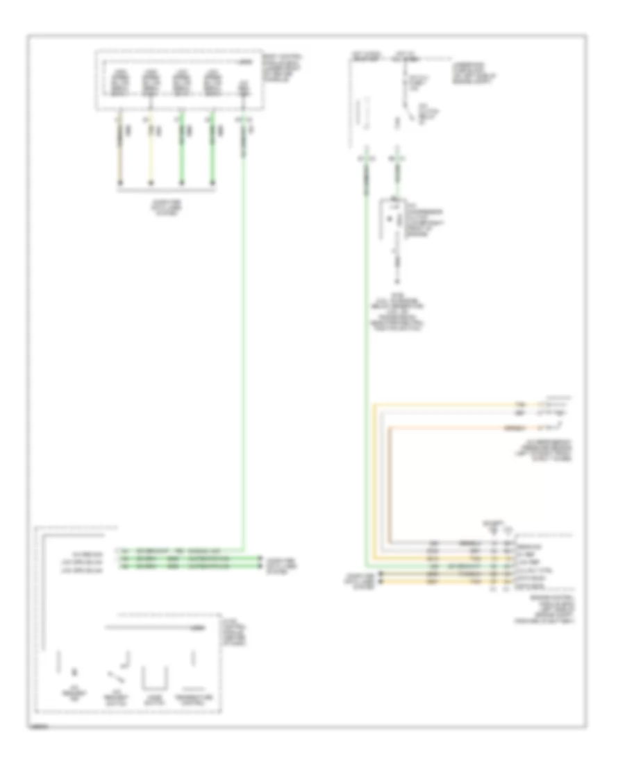
Compressor Wiring Diagram for Chevrolet Malibu LS 2007
 https://portal-diagnostov.com/license.html
Automotive Electricians Portal FZCO
Automotive Electricians Portal FZCO
https://portal-diagnostov.com/license.html
https://portal-diagnostov.com/license.html
Automotive Electricians Portal FZCO
Automotive Electricians Portal FZCOList of elements for Compressor Wiring Diagram for Chevrolet Malibu LS 2007:
- (automatic a/c)
- (manual a/c)
- 2.2l
- 5v ref
- A/c clu fuse 1 10a
- A/c clutch relay
- A/c compressor clutch (lower right front of engine)
- A/c refrigerant pressure sensor (left of right front strut tower)
- A/c req sig
- A/c request ind
- A/c request switch
- Body control module (bcm) (under front of center console)
- Clu rly ctrl
- Computer data lines system
- Data bus+
- Data bus-
- E1 c2
- E8 c1
- Engine control module (ecm) (left side of engine compt, forward of battery)
- Except 2.2l
- G106 (2.2l: on engine, below generator) (3.5l: on transmission, near park/neutral position switch)
- High speed gm lan serial data +
- High speed gm lan serial data -
- Hot at all times
- Hot in run or start
- Hvac control module (center of dash)
- Logic
- Low ref
- Low spd gmlan
- Low speed gm lan serial data
- Mode switch
- Sens sig
- Tan
- Temperature control
- Underhood fuse block (on left side of engine compt)
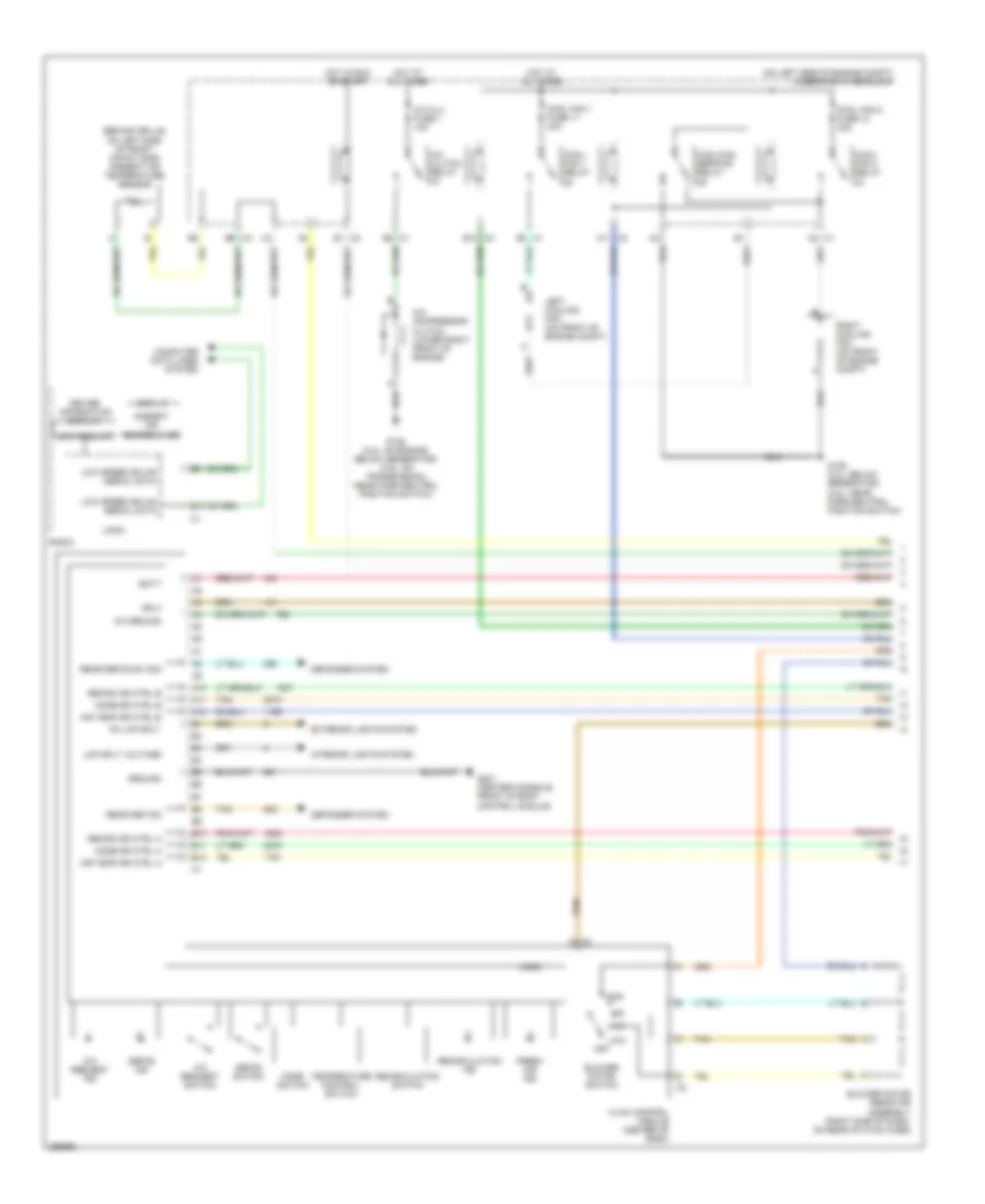
Manual A/C Wiring Diagram (1 of 2) for Chevrolet Malibu LS 2007
 https://portal-diagnostov.com/license.html
Automotive Electricians Portal FZCO
Automotive Electricians Portal FZCO
https://portal-diagnostov.com/license.html
https://portal-diagnostov.com/license.html
Automotive Electricians Portal FZCO
Automotive Electricians Portal FZCOList of elements for Manual A/C Wiring Diagram (1 of 2) for Chevrolet Malibu LS 2007:
- (behind grille, on left side of front impact bar) ambient air temperature sensor
- (on left side of engine compt) underhood fuse block
- A/c clu fuse 1 10a
- A/c clutch relay
- A/c compressor clutch (lower right front of engine)
- A/c req sig
- A/c request ind
- A/c request switch
- A10
- A11
- A11 c2
- A12
- A2 c1
- Air temp dr ctrl a
- Air temp dr ctrl b
- Ambient air temperature
- B10
- B10 c2
- B11
- B12
- B9 c3
- Batt
- Blower motor resistor assembly (right side of dash, on rear of hvac case)
- Blower motor switch
- C1 e3
- C2 g
- Computer data lines system
- Cool fan 1 fuse 17 30a
- Cool fan 2 fuse 18 30a
- Cool/ fan 1 relay
- Cool/ fan 2 relay
- Cool/fan ser/par relay
- Defog ind
- Defog switch
- Defogger system
- Display
- Driver information display
- E1 c2
- E8 c1
- Exterior lights system
- Fresh air ind
- G106 (2.2l: below generator) (3.5l: near park/neutral position switch)
- G106 (2.2l: on engine, below generator) (3.5l: on transmission, near park/neutral position switch)
- G201 (center console, front of body control module)
- Ground
- High
- Hot at all times
- Hot in run or start
- Hvac control module (center of dash)
- Ign 3
- Interior lights system
- Left cooling fan (on front of engine compt)
- Lmp sply voltage
- Logic
- Low
- Low coolant
- Low speed gmlan serial data
- Mode dr ctrl a
- Mode dr ctrl b
- Mode switch
- Off
- Pk lmp sply
- Radio
- Rear def ind
- Rear defog sw sig
- Recirc dr ctrl a
- Recirc dr ctrl b
- Recirculation ind
- Recirculation switch
- Right cooling fan (on front of engine compt)
- Tan
- Temperature control switch
Manual A/C Wiring Diagram (2 of 2) for Chevrolet Malibu LS 2007
 https://portal-diagnostov.com/license.html
Automotive Electricians Portal FZCO
Automotive Electricians Portal FZCO
https://portal-diagnostov.com/license.html
https://portal-diagnostov.com/license.html
Automotive Electricians Portal FZCO
Automotive Electricians Portal FZCOList of elements for Manual A/C Wiring Diagram (2 of 2) for Chevrolet Malibu LS 2007:
- (on engine coolant surge tank) coolant level switch
- 2.2l
- 5v ref 2
- A/c refrigerant pressure sensor (left of right front strut tower)
- A/c req sig
- After blow
- Air temperature actuator (on top right side of dash)
- Ambient air temp sensor signal
- Blower motor (below right side of dash)
- Body control module (bcm) (under front of center console)
- C4 b3
- Clu rly ctrl
- Computer data lines system
- Coolant level sw
- Coolant temp ind
- D4 c4
- Data bus+
- Data bus-
- Data link connector (dlc) (below left side of dash, near steering column)
- Ect sens sig
- Engine control module (ecm) (left side of engine compt, forward of battery)
- Engine coolant temperature (ect) sensor (2.2l: on top rear of engine) (3.5l: on right cylinder head, above transmission) (3.9l: in rear of left cylinder head)
- Except 2.2l
- G109 (near windshield wiper fluid reservoir)
- G203 (center console, front of body control module)
- Gnd
- High spd rly ctrl
- High speed gm lan serial data +
- High speed gm lan serial data -
- Hot at all times
- Hvac blower fuse 20a
- Hvac blower high relay
- Hvac ctrl (batt) fuse 10a
- Hvac ctrl (ign) fuse 10a
- Ign
- Instrument panel cluster (ipc)
- Logic
- Low ref
- Low spd rly ctrl
- Low speed gm lan serial data
- Low speed gmlan serial data
- Mode actuator (on left side of hvac case)
- Recirculation actuator (on right side of hvac case)
- Run relay
- Run rly ctrl
- Sens sig
- Serial data
- Tan

 Čeština
 Dansk
Dansk Deutsch
 Ελληνικά
 English
 English
 Español
 Suomi
Suomi Français
 Français
 עברית
עברית Hrvatski
 Magyar
 Italiano
 日本語
日本語 한국어
한국어 Nederlands
 Polski
 Português
 Português
 Română
 Русский
 Slovenčina
 Slovenščina
 Svenska
 中文 (中国)
