Čeština
 Dansk
Dansk Deutsch
 Ελληνικά
 English
 English
 Español
 Suomi
Suomi Français
 Français
 עברית
עברית Hrvatski
 Magyar
 Italiano
 日本語
日本語 한국어
한국어 Nederlands
 Polski
 Português
 Português
 Română
 Русский
 Slovenčina
 Slovenščina
 Svenska
 中文 (中国)

AIR CONDITIONING
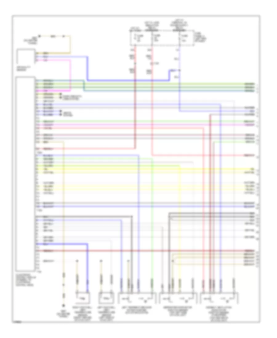
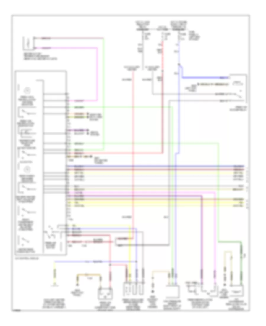
Automatic A/C Wiring Diagram (1 of 3) for Volkswagen CC R-Line 2012
List of elements for Automatic A/C Wiring Diagram (1 of 3) for Volkswagen CC R-Line 2012:

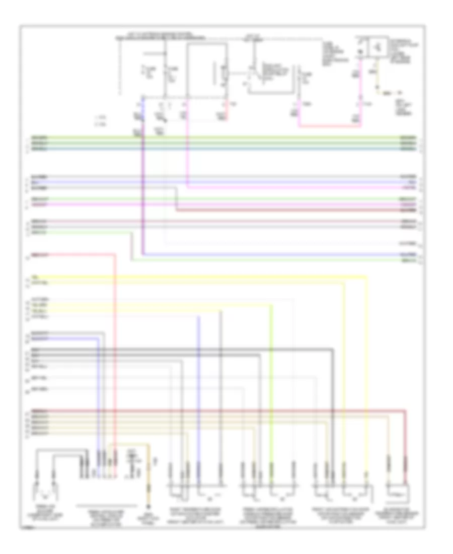
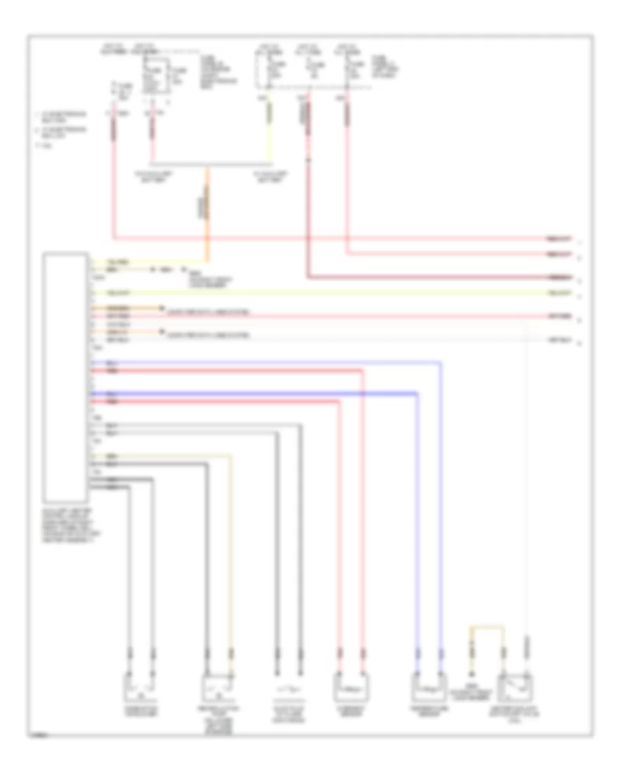
Automatic A/C Wiring Diagram (2 of 3) for Volkswagen CC R-Line 2012
List of elements for Automatic A/C Wiring Diagram (2 of 3) for Volkswagen CC R-Line 2012:
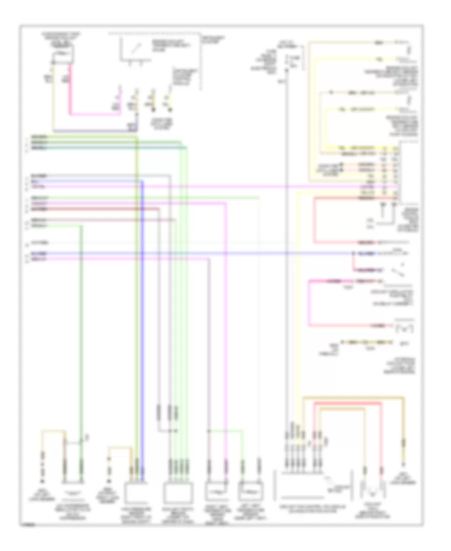
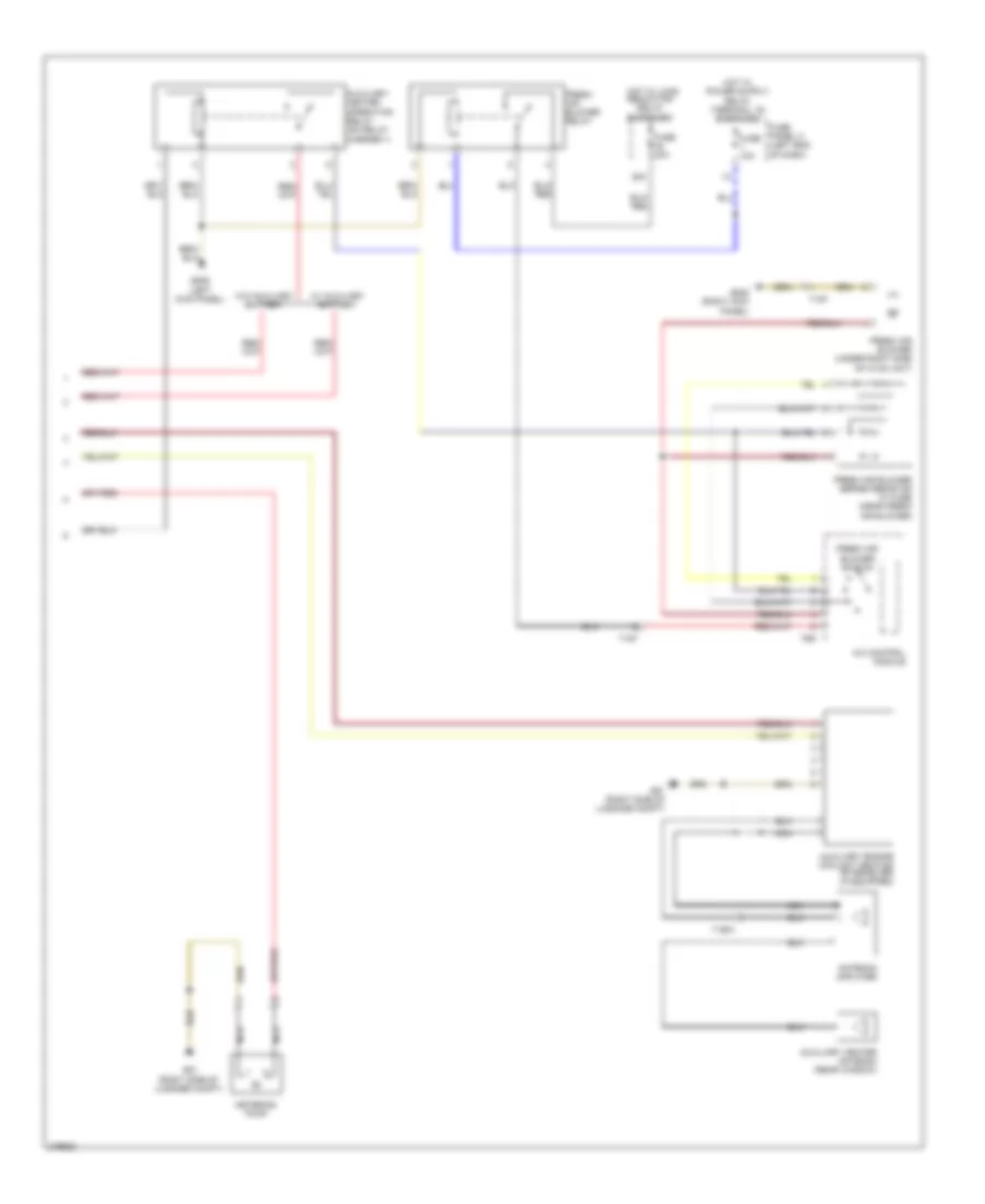
Automatic A/C Wiring Diagram (3 of 3) for Volkswagen CC R-Line 2012
List of elements for Automatic A/C Wiring Diagram (3 of 3) for Volkswagen CC R-Line 2012:
Auxiliary Heater Wiring Diagram (1 of 2) for Volkswagen CC R-Line 2012
List of elements for Auxiliary Heater Wiring Diagram (1 of 2) for Volkswagen CC R-Line 2012:
Auxiliary Heater Wiring Diagram (2 of 2) for Volkswagen CC R-Line 2012
List of elements for Auxiliary Heater Wiring Diagram (2 of 2) for Volkswagen CC R-Line 2012:
Manual A/C Wiring Diagram (1 of 2) for Volkswagen CC R-Line 2012
List of elements for Manual A/C Wiring Diagram (1 of 2) for Volkswagen CC R-Line 2012:
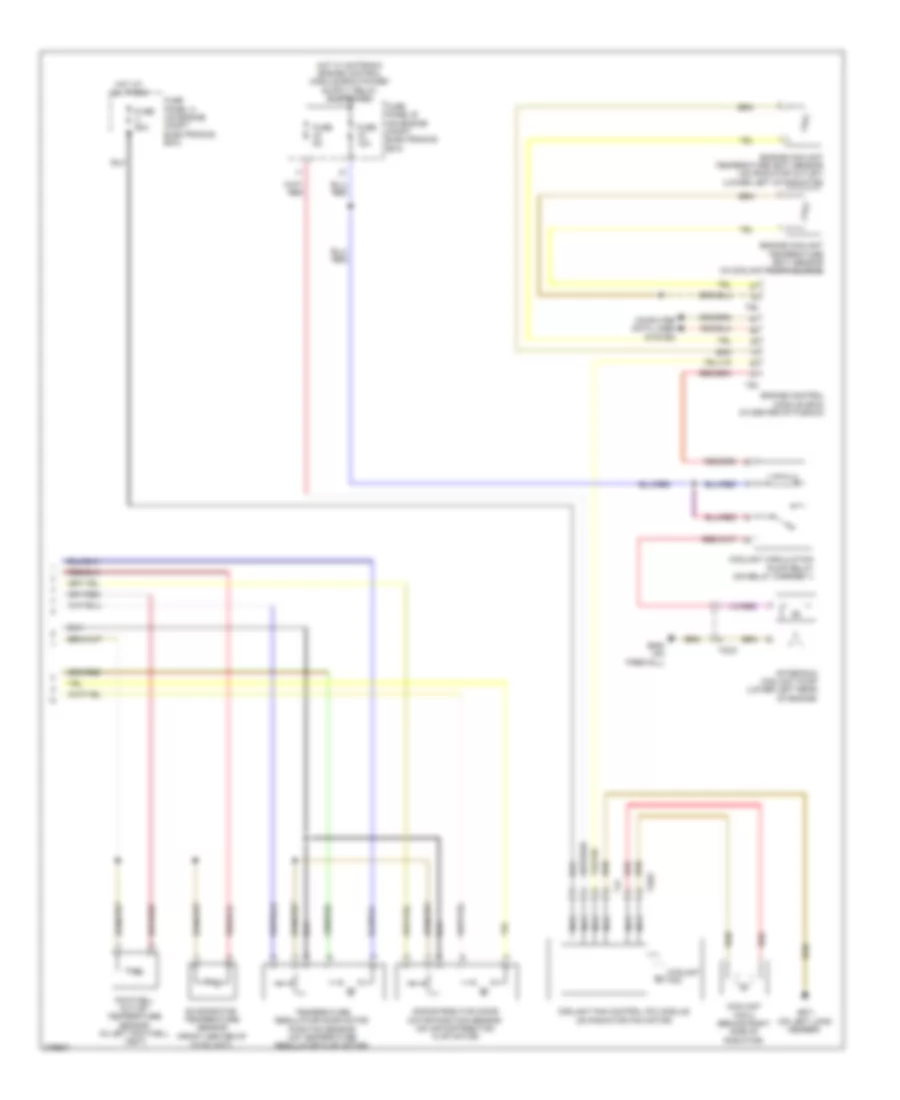
Manual A/C Wiring Diagram (2 of 2) for Volkswagen CC R-Line 2012
List of elements for Manual A/C Wiring Diagram (2 of 2) for Volkswagen CC R-Line 2012: