СИСТЕМА ПЕРЕДАЧИ ДАННЫХ
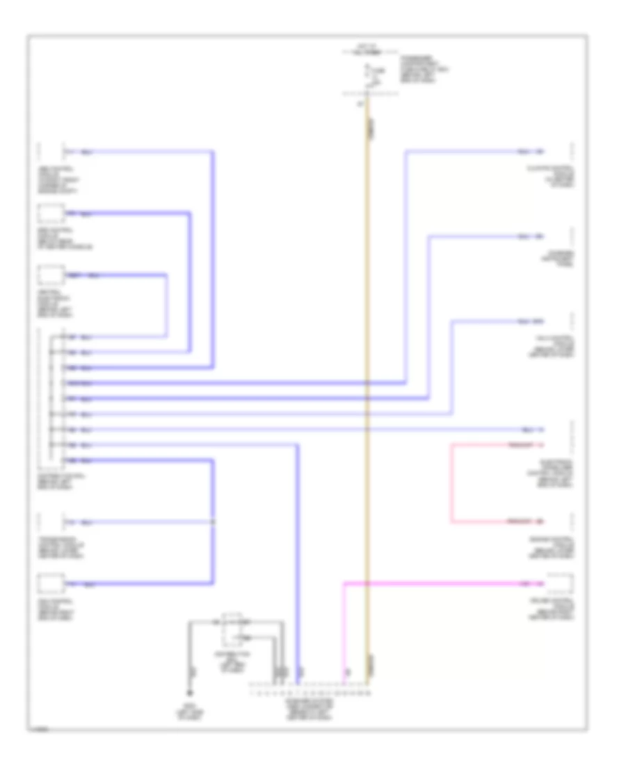
Электросхема компьютерной линии передачи данных CAN для Volvo V40 2001
 https://portal-diagnostov.com/license.html
Automotive Electricians Portal FZCO
Automotive Electricians Portal FZCO
https://portal-diagnostov.com/license.html
https://portal-diagnostov.com/license.html
Automotive Electricians Portal FZCO
Automotive Electricians Portal FZCO
Электросхема компьютерной линии передачи данных CAN для Volvo V40 2001 - Список элементов:
- (left side of dash)
- Abs control module (in right front corner of engine compt)
- B19
- B2/7
- Central electronic module (behind left end of dash)
- Climate control module (in center of dash)
- Combined instrument panel
- Cruise control module (behind right center of dash)
- Distribution rail (behind left end of dash)
- Distribution rail (left end of dash)
- Dsa control module (behind right end of dash)
- E10
- Electronic immobilizer control module (behind left end of dash)
- Engine control module (behind lower center of dash)
- Fuse 15a
- G202
- Hot at all times
- On-board system (obd) connector (beneath left center of dash)
- Passenger compartment fuse & relay box (behind left end of dash)
- Srs control module (below rear of center console)
- Transmission control module (behind lower center of dash)
- Vgla control module (behind lower center of dash)
 Čeština
 Dansk
Dansk Deutsch
 Ελληνικά
 English
 English
 Español
 Suomi
Suomi Français
 Français
 עברית
עברית Hrvatski
 Magyar
 Italiano
 日本語
日本語 한국어
한국어 Nederlands
 Polski
 Português
 Português
 Română
 Русский
 Slovenčina
 Slovenščina
 Svenska
 中文 (中国)
 Türkçe
