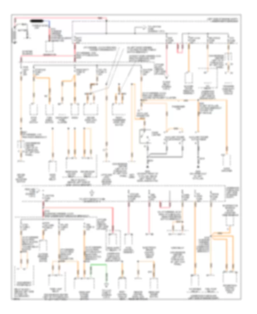
POWER DISTRIBUTION
Power Distribution Wiring Diagram (1 of 3) for Chevrolet Astro 2005
 https://portal-diagnostov.com/license.html
Automotive Electricians Portal FZCO
Automotive Electricians Portal FZCO
https://portal-diagnostov.com/license.html
https://portal-diagnostov.com/license.html
Automotive Electricians Portal FZCO
Automotive Electricians Portal FZCO
List of elements for Power Distribution Wiring Diagram (1 of 3) for Chevrolet Astro 2005:
- (i/p harness, 10.5 cm from bcm connectors breakout)
- (i/p harness, 13cm from i/p fuse block) s209 red
- (in i/p harness 6.5 cm from relay blocks breakout, toward relay blocks) s220
- (in i/p harness, 5.5 cm from c201 breakout, toward instrument cluster) s210
- (in l/p harness, 28 cm from i/p fuse block, near park brake switch breakout) s327
- (in left door harness, 17 cm from power window switch breakout)
- (in right door harness, 6 cm from power door lock switch breakout)
- (left side of engine compt) underhood fuse block
- (not used)
- A/c comp fuse 10a
- A/c enable relay
- A/c relay
- A12
- Abs fuse 60a
- Atc fuse 20a
- Audio amplifier
- Aux pwr fuse 7 25a
- Auxiliary power outlet-rear
- Auxiliary power outlets-front 1&2
- Batt fuse 50a
- Battery
- Blower motor resistor assembly
- Body control module (bcm)
- Cig ltr fuse 13 20a
- Cigar lighter
- Convenience center (left of i/p fuse block, by left kick panel)
- Convenience center (left of i/p fuse block, e by left kick panel)
- Ctsy fuse 3 20a
- Data link connector (dlc)
- Door lock relay
- Driver door lock switch
- Driver door unlock relay
- Driver seat adjuster switch
- E10
- Ecm-b fuse 20a
- Electronic brake control module (ebcm)
- Evaporative emission (evap) canister vent solenoid
- From abs fuse a (diagram 1 of 3)
- Front passenger door lock switch
- Frt hvac fuse 30a
- Fuel pump relay
- Fusible link
- G200 (on right front of "a" pillar, above left front of door jamb switch)
- G400 (on upper half of left "d" pillar)
- Generator
- Headlamp & panel dimmer switch
- Headlamp dimmer switch
- Headlamps relay
- Horn fuse 20a
- Horn relay
- Htd mir/ rr defog fuse 40a
- Hvac control assembly
- I/p fuse block (behind left side of dash)
- Inadvertent power relay
- Instrument panel cluster
- Liftglass lock/ unlock release switch
- Lighting fuse 40a
- Near park brake switch breakout) s330
- Outside rearview mirror switch
- Park lamp relay
- Passenger van
- Pk lps fuse 9 20a
- Powertrain control module (pcm)
- Pwr accy cb 25a
- Radio
- Radio batt fuse 19 10a
- Rap fuse 40a
- Rear door unlock relay
- Red
- Relay block 1 (behind left side of dash, on dlc bracket)
- Remote control door lock receiver (rcdlr)
- Rr htr/ac fuse 30a
- S109 (in engine harness, 4 cm from underhood fuse block breakout)
- S121 (in engine harness, 12 cm from starter solenoid connector)
- S133 (in engine harness, 2.5 cm from underhood fuse block breakout)
- S319
- S322 (in left "b" pillar, 4 cm from breakout toward top of vehicle)
- S500
- S600
- Starter solenoid
- Stop lamp switch
- Stop/haz fuse 1 20a
- Tbc fuse 15 10a
- To illum fuse 14 (diagram 3 of 3)
- To lighting fuse (diagram 1 0f 3)
- To rap relay (diagram 3 of 3)
- To upfitter-batt fuse (diagram 2 of 3)
- Transfer case shift control module
- Turn signal switch
- Underhood fuse block (left side of engine compt)
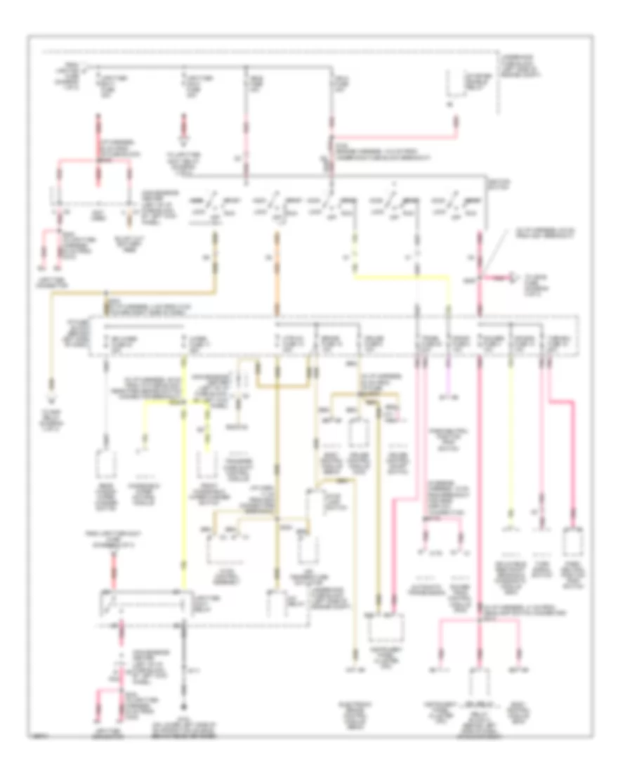
Power Distribution Wiring Diagram (2 of 3) for Chevrolet Astro 2005
 https://portal-diagnostov.com/license.html
Automotive Electricians Portal FZCO
Automotive Electricians Portal FZCO
https://portal-diagnostov.com/license.html
https://portal-diagnostov.com/license.html
Automotive Electricians Portal FZCO
Automotive Electricians Portal FZCOList of elements for Power Distribution Wiring Diagram (2 of 3) for Chevrolet Astro 2005:
- (i/p harn, 17 cm from bcm connectors breakout)
- (i/p harness, 28 cm from i/p fuse block) s303
- (in engine harness, 18 cm from breakout for mass airflow, toward c100) s115
- (in i/p harness, 20 cm from i/p fuse block)
- (in i/p harness, 38 cm from i/p fuse block, near park brake switch connector breakout) s324
- (in i/p harness, 41 cm from headlamp switch connector) s213
- (in i/p harness, 6.5 cm from c201 breakout)
- (not used)
- 40 cm from c333)
- A/c relay
- A13
- Acc
- Air bag fuse 10 10a
- Air temperature actuator
- Automatic transmission
- B10
- Body control module (bcm)
- Body control module (ebcm)
- Brake fuse 18 10a
- C175
- Convenience center (left of i/p fuse block, a by left kick panel)
- Convenience center (left of i/p fuse block, by left kick panel)
- Crank fuse 8 10a
- Cruise control module (ccm)
- Cruise control on/off switch
- Cruise fuse 6 10a
- D5 red/
- Drl relay
- E10
- Electronic brake control module (ebcm)
- From lighting c
- From upfitter-accy fuse (diagram 2 of 3)
- Front windshield wiper/washer switch
- Fuse (diagram 1 of 3)
- G104 (on lower left side of evaporative housing, behind receiver drier)
- Gauges fuse 4 10a
- Htr-a/c fuse 12 20a
- Hvac control assembly
- I/p fuse block (behind left side of dash)
- Ign-a fuse 40a
- Ign-b fuse 40a
- Ignition switch
- Inflatable restraint sensing & diagnostic module (sdm)
- Instrument panel cluster (ipc)
- Lock
- Off
- Park/ neutral position (pnp) switch
- Park/neutral position (pnp) switch
- Pnk
- Power- train control module (pcm)
- Rear window wiper/ washer switch
- Red
- Relay block 2 (behind left side of dash, on dlc bracket)
- Rr wiper fuse 23 20a
- Run
- S108 (engine harness, 10.5 cm from underhood fuse block breakout)
- S111
- S201
- S203 (in i/p harness, 4 cm from c100, toward right side of dash)
- S205
- S224
- S240 (in upfitter harness, red 30 cm from c210)
- S242 (in upfitter harness, pnk
- Start
- Starter enable relay
- Stop lamp switch
- To ign-e fuse (diagram 3 of 3)
- To rap relay (diagram 3 of 3)
- To upfitter accy relay (diagram 2 of 3)
- Trans fuse 20 10a
- Transfer case shift control module
- Turn signal switch
- Turn-b/u fuse 16 20a
- Underhood fuse block (left side of engine compt)
- Upfitter accy relay
- Upfitter connector
- Upfitter- accy fuse 30a
- Upfitter- batt fuse 30a
- Windshield wiper motor & module
- Wiper fuse 17 25a
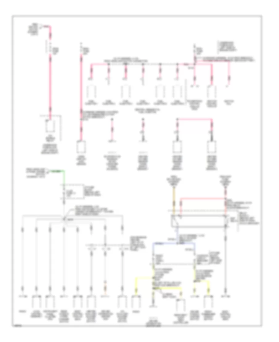
Power Distribution Wiring Diagram (3 of 3) for Chevrolet Astro 2005
 https://portal-diagnostov.com/license.html
Automotive Electricians Portal FZCO
Automotive Electricians Portal FZCO
https://portal-diagnostov.com/license.html
https://portal-diagnostov.com/license.html
Automotive Electricians Portal FZCO
Automotive Electricians Portal FZCOList of elements for Power Distribution Wiring Diagram (3 of 3) for Chevrolet Astro 2005:
- (in engine harness, 16 cm from breakout to mass airflow sensor, behind battery)
- (in engine harness, 9 cm from a/c low-pressure cut-off switch breakout) s119
- (in i/p harness, 10.5 cm from convenience center) s305
- (in i/p harness, 14 cm relay blocks breakout) s253
- (in i/p harness, 14.5 cm from i/p fuse block) s246
- (in i/p harness, 4 cm from instrument cluster connector breakout, toward right side of dash)
- (in i/p harness, 41 cm from headlamp switch connector) s123
- A/c auxiliary blower motor switch
- A/c enable relay
- Body control module (bcm)
- C10
- Central sequential fuel injection
- Convenience center (left of i/p fuse block, by left kick panel)
- Driver information center (dic)
- Driver window master switch
- Ecm-i fuse 20a
- Eng-i fuse 20a
- Evaporative emission (evap) canister purge solenoid
- From headlamp & panel dimmer d switch (diagram 1 of 3)
- From ignition f switch (diagram 2 of 3)
- From rap fuse (diagram 1 of 3)
- From splice s203 (diagram 2 of 3)
- Front passenger window switch
- Fuel injector 1
- Fuel injector 2
- Fuel injector 3
- Fuel injector 4
- Fuel injector 5
- Fuel injector 6
- Heated oxygen sensor (ho2s) bank 1 sensor 1
- Heated oxygen sensor (ho2s) bank 1 sensor 2
- Heated oxygen sensor (ho2s) bank 2 sensor 1
- Heater auxiliary blower motor switch
- Hvac control assembly
- I/p fuse block (behind left side of dash)
- Ign-e fuse 10a
- Ignition coil
- Ignition control module
- Illum fuse 14 10a
- Instrument panel cluster (ipc)
- Mass airflow (maf) sensor
- Nca
- Pnk
- Powertrain control module (pcm)
- Radio
- Radio/ accy fuse 2 10a
- Rap relay
- Rear seat audio (rsa) controller
- Rear window wiper/ washer switch
- Red
- Relay block 2 (behind left side of dash, on dlc bracket)
- S116
- S219
- S252 (in i/p harness, 20 cm from relay red blocks breakout)
- Underhood fuse block (left side of engine compt)
- W/ rear seat audio
- Windows circuit breaker 25a

 Čeština
 Dansk
Dansk Deutsch
 Ελληνικά
 English
 English
 Español
 Suomi
Suomi Français
 Français
 עברית
עברית Hrvatski
 Magyar
 Italiano
 日本語
日本語 한국어
한국어 Nederlands
 Polski
 Português
 Português
 Română
 Русский
 Slovenčina
 Slovenščina
 Svenska
 中文 (中国)
