POWER DISTRIBUTION
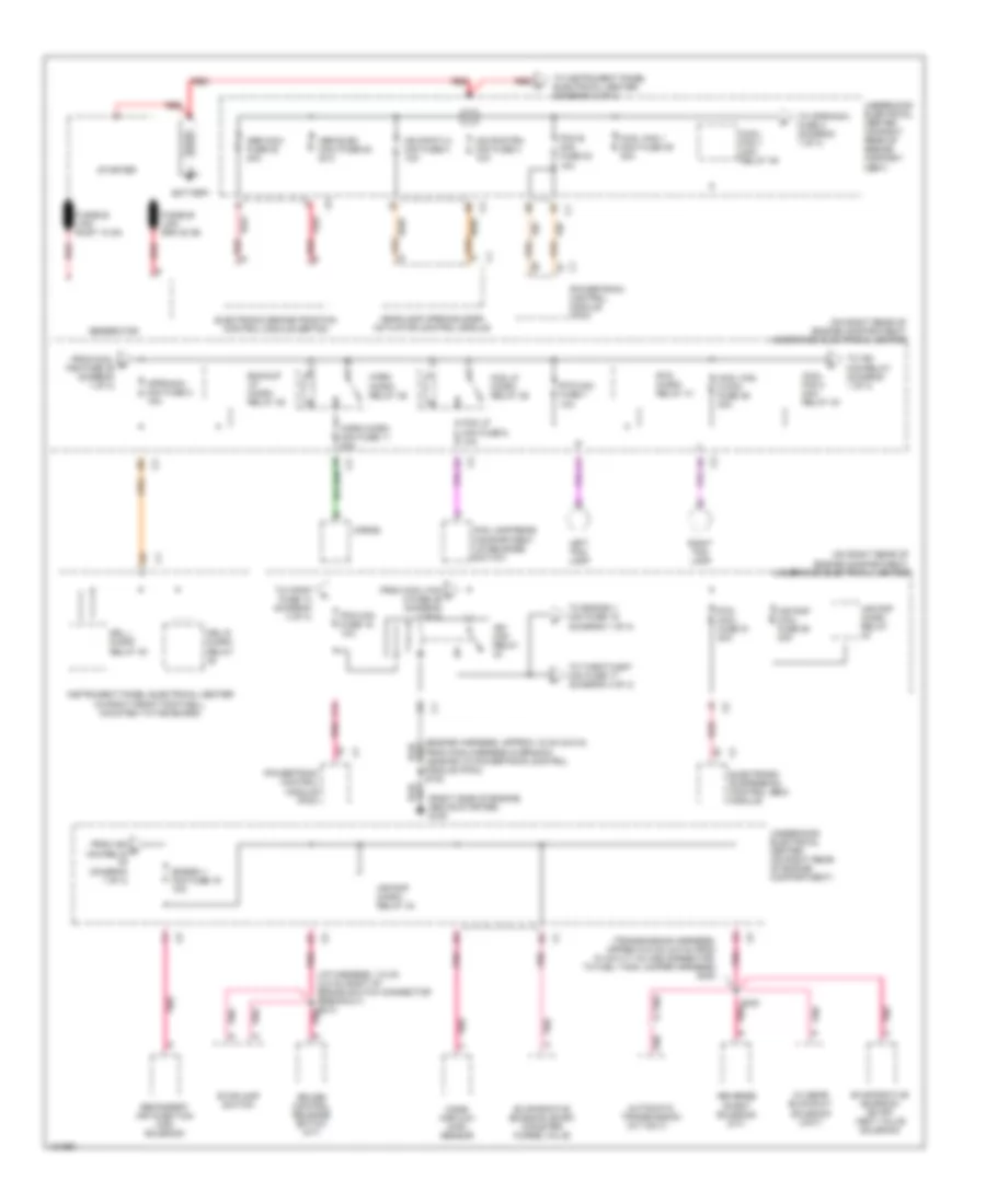
Power Distribution Wiring Diagram (1 of 4) for Chevrolet Corvette 2000
 https://portal-diagnostov.com/license.html
Automotive Electricians Portal FZCO
Automotive Electricians Portal FZCO
https://portal-diagnostov.com/license.html
https://portal-diagnostov.com/license.html
Automotive Electricians Portal FZCO
Automotive Electricians Portal FZCO
List of elements for Power Distribution Wiring Diagram (1 of 4) for Chevrolet Corvette 2000:
- (a/t only)
- (diagram 1 of 4)
- (engine harness, approx 15 cm (5.9 in) from main harness in branch leading to powertrain control module (pcm)) s120
- (i/p harness, 7.5 cm (2.9 in) right of brake switch connector breakout) s213
- (on right rear of engine compartment) underhood electrical center
- (right side of engine, above starter) g120
- (transmission harness, approx 6.5 cm (2.9 in) from 10 cavity in-line connector, to fuel tank jumper harness) s400
- 2-3 gear blockout solenoid (unit)
- Abs elec maxi fuse 53 20a
- Abs maxi fuse 52 40a
- Air pmp maxi fuse 50 20a
- Air pmp micro relay
- Air pmp micro- relay 33
- Aproach mini fuse 2 15a
- Automatic transmission
- Backup lp micro- relay 38
- Battery
- Cool fan 1 maxi fuse 49 30a
- Cool fan 1 mini- relay 45
- Cool fan 2 maxi fuse 46 30a
- Cool fan 2 mini- relay 43
- Cruise control release switch (m/t)
- Drl l micro- relay 40
- Drl r micro- relay
- Electronic brake/traction control module (ebtcm)
- Electronic suspension control (esc) module
- Engign 1 mini fuse 19 10a
- Evaporative emission (evap) canister purge valve
- Evaporative emission (evap) vent valve solenoid
- F11
- Fog lamp/rear compartment lid release switch
- Fog lp micro- relay 39
- Fog lp mini fuse 6 10a
- From cool b fan fuse 49 (diagram 1 of 4)
- From cool fan c 2 fuse 46 (diagram 1 of 4)
- From ign d mini-relay
- Fusible link gra 20 ga
- Fusible link rust 10 ga
- Generator
- Hdlpmotlh mini fuse 4 10a
- Hdlpmotrh mini fuse 3 10a
- Headlamp opening door actuator control module
- Horn micro mini fuse 11 20a
- Horn micro- relay 36
- Horns
- Ign mini- relay
- Instrument panel electrical center (in right front footwell, mounted to toe board)
- Left fog lamp
- Mass airflow (maf) sensor
- Pcm b mini fuse 23 10a
- Pcm mini fuse 16 10a
- Pnk
- Pnk e
- Powertrain control module (pcm)
- Red
- Reverse inhibit solenoid (m/t)
- Right fog lamp
- Rtd maxi fuse 51 20a
- Rtd micro- relay 41
- Rtd mini fuse 7 10a
- S400
- Secondary air injection (air) solenoid
- Starter
- Stoplamp switch
- To aproach fuse 2 (diagram 1 of 4)
- To engign 1 mini fuse 19 (diagram 1 of 4)
- To f/pmp fuse 13 (diagram 4 of 4)
- To ign mini-relay (diagram 1 of 4)
- To instrument panel electrical center (diagram 2 of 4)
- To throt-cont mini fuse 17 (diagram 4 of 4)
- Underhood electrical center (on right rear of engine compart- ment)
- Underhood electrical center (on right rear of engine compartment)
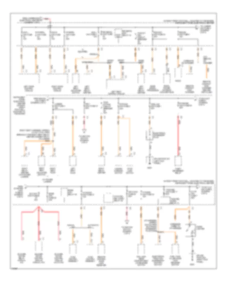
Power Distribution Wiring Diagram (2 of 4) for Chevrolet Corvette 2000
 https://portal-diagnostov.com/license.html
Automotive Electricians Portal FZCO
Automotive Electricians Portal FZCO
https://portal-diagnostov.com/license.html
https://portal-diagnostov.com/license.html
Automotive Electricians Portal FZCO
Automotive Electricians Portal FZCOList of elements for Power Distribution Wiring Diagram (2 of 4) for Chevrolet Corvette 2000:
- (i/p harness, approx 22.5 cm from elctronic accessory plug conn)
- (in right front footwell, mounted to toe board) instrument panel electrical center
- (right seat harness, approx 4.0 cm (1.5 in), from breakout for right seat relay center connector c1) (w/lumbar) s300
- (w/ power lumbar)
- A12
- Automatic a/c
- B11
- B12
- Base seat
- Blo mot maxi fuse 30a
- Blower motor control module (auto a/c)
- Blower motor control module (manual a/c)
- Blower motor relay (manual a/c)
- Bose mini fuse 28 20a
- Bose mini- relay 45
- Bose signal processor
- C/ltr mini fuse 7 25a
- C11
- C12
- Cigar lighter
- Cnsl cig mini fuse 1 20a
- Cont- act
- Dcm l mini fuse 10a
- Dcm r mini fuse 10a
- E12
- Electronic accessory plug
- Electronic traction/ suspension control switch
- F/tnkdr mini fuse 32 15a
- F12
- Fog lamp/ rear compartment lid release switch
- From rdo/cd e mini fuse 5 (diagram 2 of 4)
- From starter maxi fuse 52 (diagram 2 of 4)
- From underhood electrical center (diagram 1 of 4)
- Fuel tank filler door lock release switch
- G200
- G203
- Hazard warning switch
- Htchtrk rel micro- relay 39
- Hvac control assembly
- Hvaccon mini fuse 27 10a
- If equipped
- Ign 1 maxi fuse 47 60a
- Ign 2 maxi fuse 50 60a
- Instrument panel electrical center (in right front footwell, mounted to toe board)
- Left door control module
- Left seat adjuster switch
- Left seat control module
- Left seat pump
- Left seat relay center
- Lumbar mini fuse 3 15a
- Manual a/c
- Nca
- Pwr st/ drv circuit breaker 20a
- Pwr st/pas circuit breaker 20a
- Pwrfdl mini fuse 25a
- Pwrfdr mini fuse 25a
- Radio
- Radio power antenna (convertible)
- Rdo/ant mini fuse 24 20a
- Rdo/cd mini fuse 5 15a
- Red
- Remote compact disc changer
- Remote compact disc changer (dealer installed)
- Remote control door lock receiver
- Right door control module
- Right relay center
- Right relay center (w/o power lumbar)
- Right seat adjuster switch
- Right seat pump
- Rr defog maxi fuse 40a
- Rr defog mini- relay 44
- S212
- Scm l mini fuse 4 10a
- Splice pack 201 (left kick panel)
- Splice pack 202 (right kick panel)
- Sport seat
- Starter maxi fuse 52 60a
- Stop lamp switch
- Stp/haz mini fuse 8 20a
- Theft deterrent relay
- To blo mot fuse 51 (diagram 2 of 4)
- To ignition switch (diagram 3 of 4)
- To lumbar mini fuse 3 (diagram 2 of 4)
- To pk t/lp mini fuse 6 (diagram 3 of 4)
- Tonn rel micro- relay 41
- Tonn rel mini fuse 17 10a
- W/o remote cd changer
- W/remote cd changer
- Wire ends taped to i/p harness
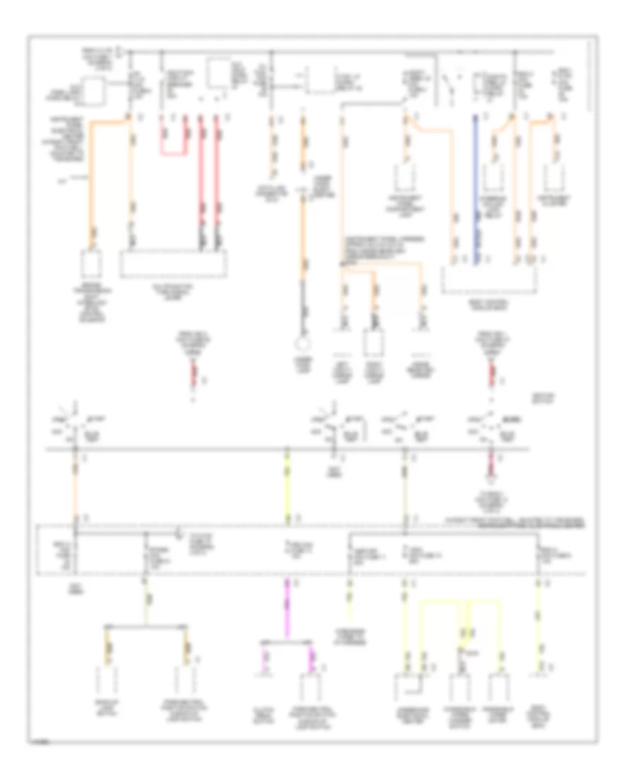
Power Distribution Wiring Diagram (3 of 4) for Chevrolet Corvette 2000
 https://portal-diagnostov.com/license.html
Automotive Electricians Portal FZCO
Automotive Electricians Portal FZCO
https://portal-diagnostov.com/license.html
https://portal-diagnostov.com/license.html
Automotive Electricians Portal FZCO
Automotive Electricians Portal FZCOList of elements for Power Distribution Wiring Diagram (3 of 4) for Chevrolet Corvette 2000:
- (in right front footwell, mounted to toe board) instrument panel electrical center
- (instrument panel harness, approx 22.5 cm (8.8 in) from inside rearview mirror breakout) s200
- (not used)
- A/t
- A11
- A12
- A14
- Acc
- Alc hdlp micro relay
- Alc park lamp micro relay
- Asryoff mini fuse 11 20a
- Back-up lamp switch
- Bcm 2 mini fuse 10a
- Bcm a mini fuse 9 10a
- Bcm i & ipc mini fuse 10a
- Bcm i3 mini fuse 10a
- Body control module (bcm)
- Brake/ transmission shift interlock (btsi) control solenoid
- Btsibu mini fuse 21 10a
- Bulb test
- C/l aldl mini fuse 10a
- C219
- Clutch pedal switch
- Crk mini fuse 14 10a
- Ctsy lp micro- relay 42
- D12
- Data link connector (dlc)
- From c/ltr mini fuse 7 (diagram 2 of 4)
- From ign 1 maxi fuse 47 (diagram 2 of 4)
- From ign 2 maxi fuse 50 (diagram 2 of 4)
- Hdlp maxi circuit breaker 20a
- Ignition switch
- Inside rearview mirror
- Instrument cluster
- Instrument panel compartment lamp
- Instrument panel electrical center (in right front footwell, mounted to toe board)
- Left vanity mirror lamp
- M/t
- Monit- ored ld mini fuse 2 10a
- Monito- red ld micro relay
- Multifunction turn signal lever
- Nca
- Off
- Park/neutral position switch & back-up lamp switch
- Pk t/lp mini fuse 6 10a
- Pnk
- Red
- Right vanity mirror lamp
- Start
- Steering column lock relay
- To bcmi1 mini fuse 13 (diagram 4 of 4)
- To hvac fuse 18 (diagram 4 of 4)
- Under -hood elect center
- Under- hood lamp
- Underhood electrical center
- Windshield wiper motor
- Windshield wiper/ washer switch
- Wire ends taped to i/p harness
- Wsw mini fuse 10 25a
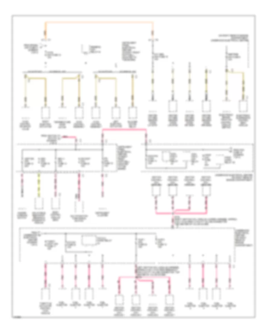
Power Distribution Wiring Diagram (4 of 4) for Chevrolet Corvette 2000
 https://portal-diagnostov.com/license.html
Automotive Electricians Portal FZCO
Automotive Electricians Portal FZCO
https://portal-diagnostov.com/license.html
https://portal-diagnostov.com/license.html
Automotive Electricians Portal FZCO
Automotive Electricians Portal FZCOList of elements for Power Distribution Wiring Diagram (4 of 4) for Chevrolet Corvette 2000:
- (diagram 3 of 4)
- (on right rear of engine compartment) underhood electrical center
- A/c clu micro relay
- A/c mini fuse 24 10a
- A13
- A6 (left ignition coil module harness, approx 5 cm (1.9 in) from breakout for 8 cavity in-line connector, top center of valve cover) s103
- Abstrns mini fuse 5 10a
- B12
- Bcm i1 mini fuse 13 10a
- Blower motor relay
- Body control module (bcm)
- Coil
- Cool fan 2 mini relay
- Cool fan 3 mini relay
- Coolfan 3 mini fuse 14 10a
- Cr cont mini fuse 20 10a
- D13
- Electrical center (diagram 1 of 4)
- Electronic brake/ traction control module (ebtcm)
- Electronic suspension control (esc) module
- F/pmp micro- relay 35
- F/pmp mini fuse 20a
- From btsibu mini fuse 21 (diagram 3 of 4)
- From ignition switch l
- From pcm fuse 16 (diagram 1 of 4)
- From underhood m
- Fuel injector
- Hazard warning switch
- Heated oxygen sensor (ho2s) (lf) b1s1
- Heated oxygen sensor (ho2s) (lr) b1s2
- Heated oxygen sensor (ho2s) (rf) b2s1
- Heated oxygen sensor (ho2s) (rr) b2s2
- Hvac control assembly
- Hvac control solenoid valve
- Hvac mini fuse 18 10a
- Hzdt/sg mini fuse 15 20a
- Ignition control/ coil module 1
- Ignition control/ coil module 2
- Ignition control/ coil module 3
- Ignition control/ coil module 4
- Ignition control/ coil module 5
- Ignition control/ coil module 6
- Ignition control/ coil module 7
- Ignition control/ coil module 8
- Inflatable restraint sensing & diagnostic module
- Injr 1 mini fuse 22 15a
- Injr 2 mini fuse 18 15a
- Instrument cluster
- Instrument panel electrical center (in right front footwell, mounted to toe board)
- Ipc mini fuse 19 10a
- Left electric actuator
- Multifunction turn signal switch
- Nca
- Oxy sen mini fuse 15 15a
- Pnk
- Pnk a11
- Pnk d5
- Right electric actuator
- Rrdefog mini- relay 44
- S102 (right ignition coil module jumper harness, approx 5 cm (1.9 in) from, 8 cavity in-line connector, top center of valve cover) c1
- Sdm mini fuse 16 15a
- Temperature door motor
- Throt- cont mini fuse 17 15a
- Throttle actuator control (tac) module
- Underhood electrical center (on right rear of engine compartment)
- W/ auto a/c
- W/ manual a/c

 Čeština
 Dansk
Dansk Deutsch
 Ελληνικά
 English
 English
 Español
 Suomi
Suomi Français
 Français
 עברית
עברית Hrvatski
 Magyar
 Italiano
 日本語
日本語 한국어
한국어 Nederlands
 Polski
 Português
 Português
 Română
 Русский
 Slovenčina
 Slovenščina
 Svenska
 中文 (中国)
