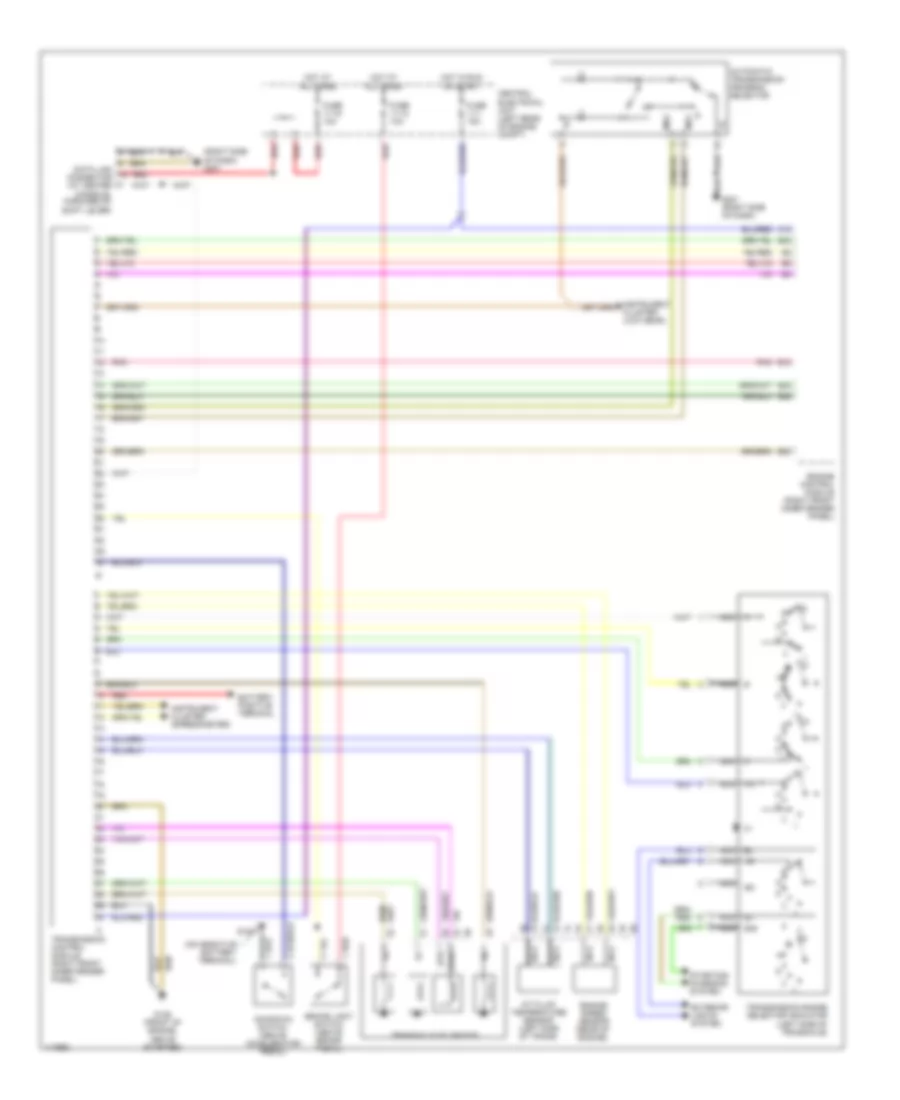
TRANSMISSION
A/T Wiring Diagram for Volvo 850 T-5 1997
 https://portal-diagnostov.com/license.html
Automotive Electricians Portal FZCO
Automotive Electricians Portal FZCO
https://portal-diagnostov.com/license.html
https://portal-diagnostov.com/license.html
Automotive Electricians Portal FZCO
Automotive Electricians Portal FZCO
List of elements for A/T Wiring Diagram for Volvo 850 T-5 1997:
- (right side of dash) g201
- 15i
- 50s
- A/t fluid temperature sensor (left side of trans)
- A12
- Automatic transmission program selector
- B12
- B20
- B24
- B26
- B42
- Battery positive terminal
- Brake light switch (above brake pedal)
- Central electrical unit (left rear of engine compt)
- Data link connector (at center console, forward of shift lever)
- Engine control module (right front inner fender panel)
- Engine speed sensor (rear of engine)
- Exterior lights system
- Fuse 11-1 15a
- Fuse 11-12 10a
- Fuse 11-15 10a
- G100
- G125 (front of engine, above starter)
- G201 (right side of dash)
- Hot at all times
- Hot in run or start
- Instrument cluster (low gear)
- Instrument cluster (speedometer)
- Kickdown switch (above accelerator pedal)
- Ms1
- Ms2
- Nca
- Pnk
- Red
- Starting/ charging system
- Sth
- Sthg
- Transaxle solenoids
- Transmission control module (right front inner fender panel)
- Transmission range selector indicator (left side of transaxle)
 Čeština
 Dansk
Dansk Deutsch
 Ελληνικά
 English
 English
 Español
 Suomi
Suomi Français
 Français
 עברית
עברית Hrvatski
 Magyar
 Italiano
 日本語
日本語 한국어
한국어 Nederlands
 Polski
 Português
 Português
 Română
 Русский
 Slovenčina
 Slovenščina
 Svenska
 中文 (中国)
 Türkçe
