ANTI-LOCK BRAKES
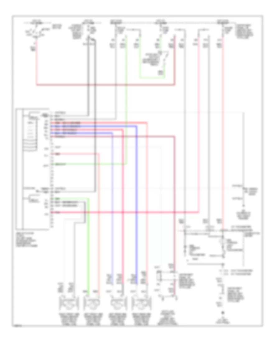
Anti-lock Brakes Wiring Diagram for Toyota ECHO 2004
 https://portal-diagnostov.com/license.html
Automotive Electricians Portal FZCO
Automotive Electricians Portal FZCO
https://portal-diagnostov.com/license.html
https://portal-diagnostov.com/license.html
Automotive Electricians Portal FZCO
Automotive Electricians Portal FZCO
List of elements for Anti-lock Brakes Wiring Diagram for Toyota ECHO 2004:
- (hatch back)
- (sedan)
- (w/ tachometer)
- (w/o tachometer)
- +bm
- Abs actuator w/ ecu (on left side of engine compt, near brake master cylinder)
- Abs fuse 60a
- Abs warning light (w/ tachometer)
- Abs warning light (w/o tachometer)
- Acc
- C13
- C14
- Combination meter
- D/g
- Data link connector (dlc) 3 (under left side of dash, near kick panel)
- Ec (on rear of left front fender)
- Ecu-ig fuse 7.5a
- F12
- Fl+
- Fl-
- Fr+
- Fr-
- Fusible link block (on left side of engine compt)
- G13
- Gauge fuse 10a
- Gnd1 +bs
- Gnd2
- Hot at all times
- Hot in on or start
- Id (at left kick panel)
- Ig1
- Ignition switch
- Instrument panel j/b (behind left side of dash, near base of "a" pillar)
- Left front abs speed sensor (mounted on left front wheel hub)
- Left rear abs speed sensor (mounted on left rear wheel hub)
- Lock
- Off
- P10
- Pnk
- Red
- Relay
- Right front abs speed sensor (mounted on right front wheel hub)
- Right rear abs speed sensor (mounted on right rear wheel hub)
- Rl+
- Rl-
- Rr+
- Rr-
- Sil
- Start
- Stop fuse 10a
- Stoplight switch (on bracket, above brake pedal)
- Stp
 Čeština
 Dansk
Dansk Deutsch
 Ελληνικά
 English
 English
 Español
 Suomi
Suomi Français
 Français
 עברית
עברית Hrvatski
 Magyar
 Italiano
 日本語
日本語 한국어
한국어 Nederlands
 Polski
 Português
 Português
 Română
 Русский
 Slovenčina
 Slovenščina
 Svenska
 中文 (中国)
 Türkçe
