ANTI-LOCK BRAKES
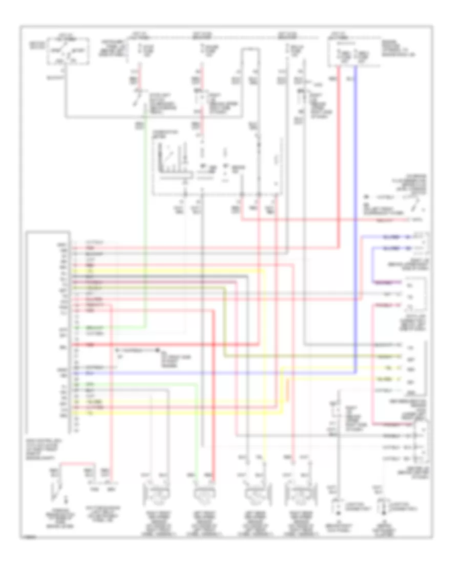
Anti-lock Brakes Wiring Diagram for Toyota Matrix XRS 2003
 https://portal-diagnostov.com/license.html
Automotive Electricians Portal FZCO
Automotive Electricians Portal FZCO
https://portal-diagnostov.com/license.html
https://portal-diagnostov.com/license.html
Automotive Electricians Portal FZCO
Automotive Electricians Portal FZCO
List of elements for Anti-lock Brakes Wiring Diagram for Toyota Matrix XRS 2003:
- (on brake fluid reservoir) brake fluid level warning switch
- +bm
- +bs
- +ig
- 4wd
- A11
- A22
- Abs 1 fuse 30a
- Abs 2 fuse 40a
- Abs deceleration sensor (4wd) (under left front seat)
- Abs ind
- Acc
- B16
- B18
- B21
- B22
- Brake ind
- Brk
- Brl
- C13
- C14
- Center j/b (behind center of dash)
- Combination meter
- D/g
- Data link connector 3 (below left side of dash)
- Daytime running light relay (on instrument panel j/b)
- Ea (at front side of right fender)
- Eb (on left front suspension tower)
- Ecu-ig fuse 10a
- Engine room r/b (integral to engine room j/b)
- Fl+
- Fl-
- Fr+
- Fr-
- Gauge fuse 10a
- Gnd
- Gnd1
- Gnd2
- Gs1
- Gs2
- Gst
- Hot at all times
- Hot in on or start
- Ie (behind instrument cluster)
- Ig (behind right kick panel)
- Ig1
- Ignition switch
- Instrument panel j/b (behind left side of dash)
- Junction connector 2
- Junction connector 7
- Left front abs speed sensor (on inside of left front wheel assembly)
- Left rear abs speed sensor (on inside of left rear wheel assembly)
- Off
- Parking brake switch (at base of park brake lever)
- Pkb
- Red
- Right front abs speed sensor (on inside of right front wheel assembly)
- Right j/b (behind upper right side of dash)
- Right rear abs speed sensor (on inside of right rear wheel assembly)
- Rl+
- Rl-
- Rr+
- Rr-
- Sil
- Skid control ecu with actuator (at right front side of engine compt)
- Sp1
- Speedometer
- Start
- Stop fuse 15a
- Stoplight switch (on bracket, above brake pedal)
- Stp
 Čeština
 Dansk
Dansk Deutsch
 Ελληνικά
 English
 English
 Español
 Suomi
Suomi Français
 Français
 עברית
עברית Hrvatski
 Magyar
 Italiano
 日本語
日本語 한국어
한국어 Nederlands
 Polski
 Português
 Português
 Română
 Русский
 Slovenčina
 Slovenščina
 Svenska
 中文 (中国)
 Türkçe
