ENGINE PERFORMANCE
2.5L
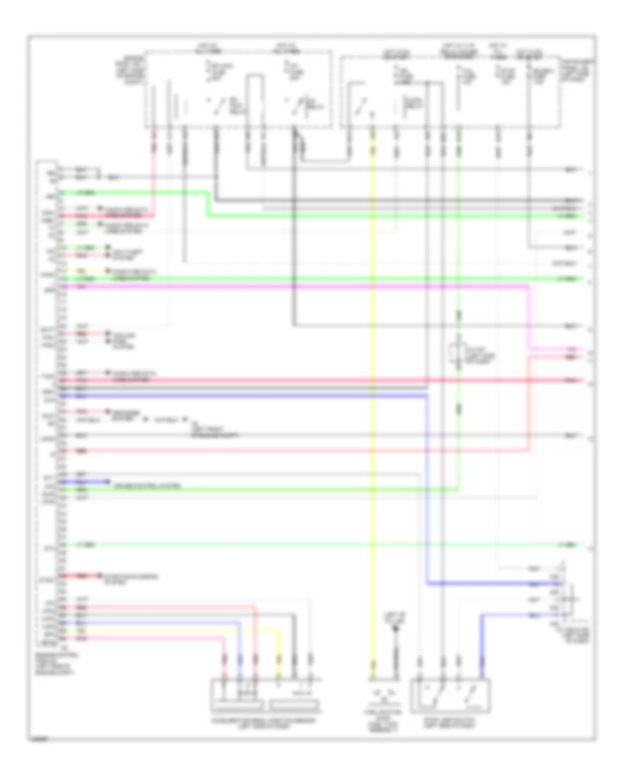
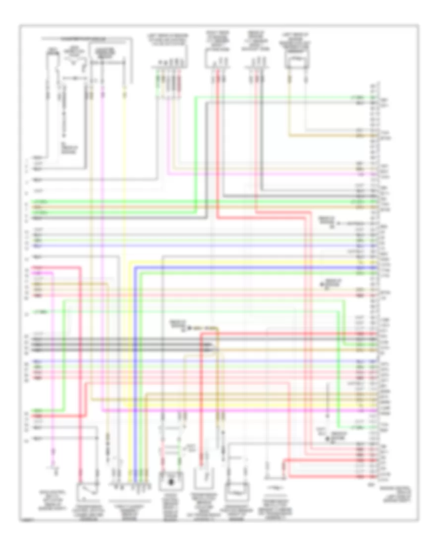
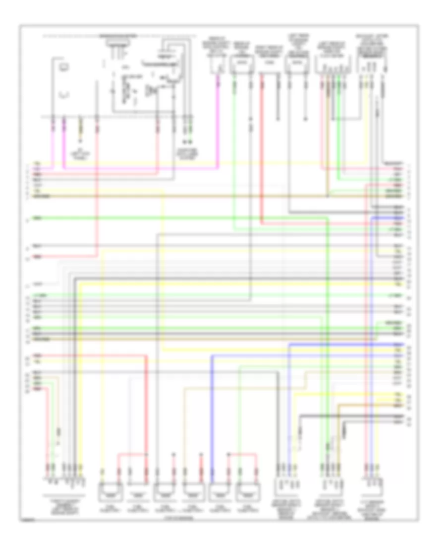
2.5L, Engine Performance Wiring Diagram (1 of 5) for Toyota RAV4 2009
 https://portal-diagnostov.com/license.html
Automotive Electricians Portal FZCO
Automotive Electricians Portal FZCO
https://portal-diagnostov.com/license.html
https://portal-diagnostov.com/license.html
Automotive Electricians Portal FZCO
Automotive Electricians Portal FZCO
List of elements for 2.5L, Engine Performance Wiring Diagram (1 of 5) for Toyota RAV4 2009:
- (left ''b'' pillar) k1
- (left side of engine compt)
- +b2
- +bm
- A/f fuse 20a
- A/f relay
- A2 (left front of engine compt)
- A35
- A38
- Accelerator pedal position sensor (left side of dash)
- Anti-theft system
- B11
- B15
- B18
- B27
- Batt
- C/opn relay
- Canh
- Canl
- Ccs
- Computer data lines system
- Cooling fans system
- Cruise control system
- Defogger system
- Efi main fuse 20a
- Efi main relay
- Els1
- Els3
- Engine control module (left side of engine compt)
- Engine room j/b 1
- Epa
- Epa2
- Fanh
- Fanl
- Fuel suction pump (fuel tank assembly)
- Gauge 2 fuse 7.5a
- Hot at all times
- Hot in on or start
- Hot w/ t-lp relay power energized
- Ign fuse 7.5a
- Igsw
- Imi
- Imo
- Instrument panel j/b (left side of dash)
- J/c a35 & a38 (left side of dash)
- J/c a37 (left side of dash)
- Mpmp
- Mrel
- Pnk
- Red
- Spd
- St1-
- Sta
- Starting/charging system
- Stop fuse 10a
- Stop lamp switch (left side of dash)
- Stp
- Stsw
- Tach
- Tail fuse 10a
- Vcp2
- Vcpa
- Vpa
- Vpa2
- Vpmp
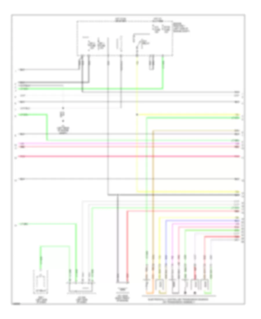
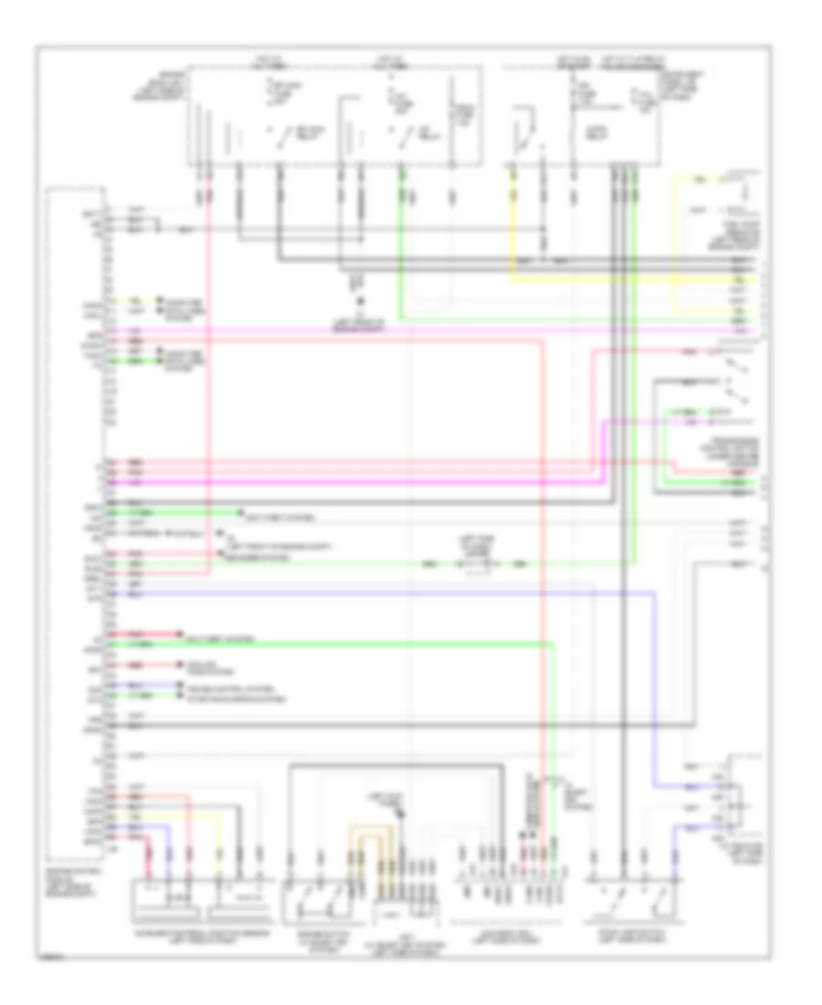
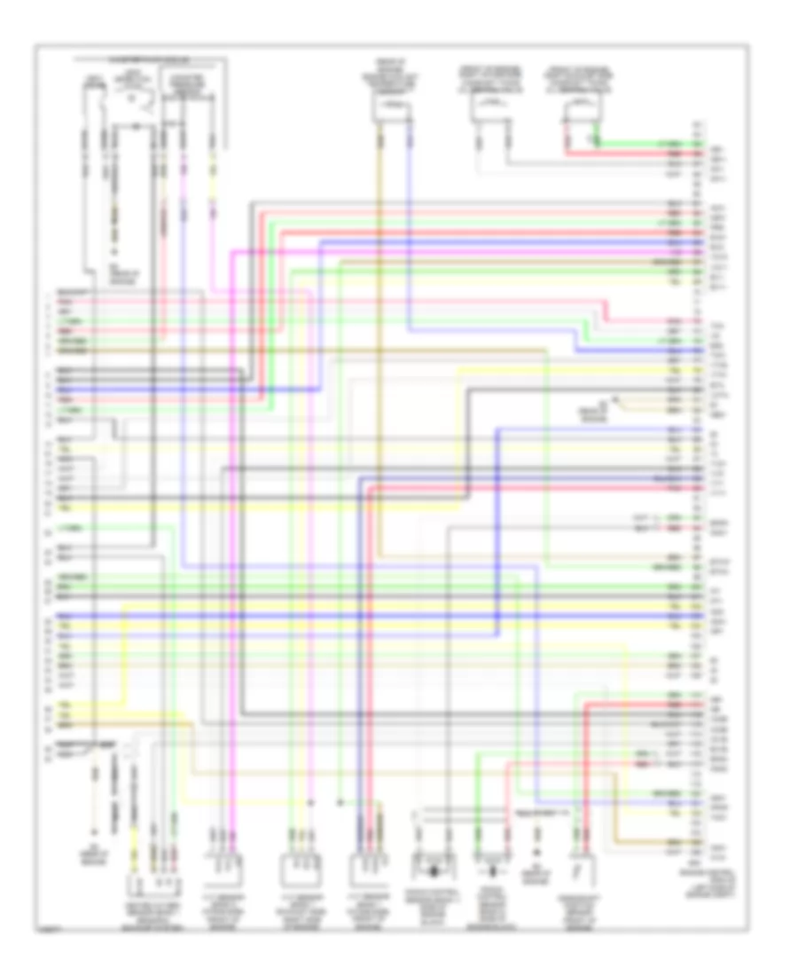
2.5L, Engine Performance Wiring Diagram (2 of 5) for Toyota RAV4 2009
 https://portal-diagnostov.com/license.html
Automotive Electricians Portal FZCO
Automotive Electricians Portal FZCO
https://portal-diagnostov.com/license.html
https://portal-diagnostov.com/license.html
Automotive Electricians Portal FZCO
Automotive Electricians Portal FZCOList of elements for 2.5L, Engine Performance Wiring Diagram (2 of 5) for Toyota RAV4 2009:
- (left side of engine compt)
- A1 (left rear of engine compt)
- Dsl
- Efi 1 fuse 10a
- Efi 2 fuse 10a
- Electronically controlled transmission solenoid (on transmission assembly)
- Engine room r/b 1
- Etcs fuse 10a
- Hot at all times
- Hot in on or start
- Ig 2 fuse 15a
- Ig 2 relay
- J/c a35 (left side of dash)
- Pnk
- R/b 7 (left side of dash)
- Red
- St relay
- Vsv (acis) (right front of engine)
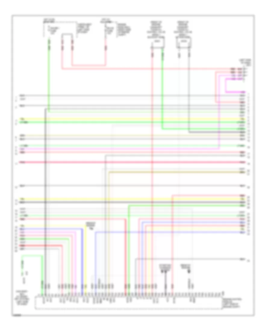
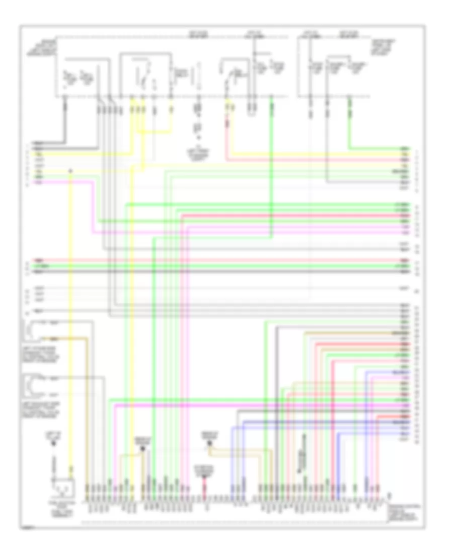
2.5L, Engine Performance Wiring Diagram (3 of 5) for Toyota RAV4 2009
 https://portal-diagnostov.com/license.html
Automotive Electricians Portal FZCO
Automotive Electricians Portal FZCO
https://portal-diagnostov.com/license.html
https://portal-diagnostov.com/license.html
Automotive Electricians Portal FZCO
Automotive Electricians Portal FZCOList of elements for 2.5L, Engine Performance Wiring Diagram (3 of 5) for Toyota RAV4 2009:
- (front of engine) camshaft timing oil control valve (bank 1 exhaust side)
- (front of engine) camshaft timing oil control valve (bank 1 intake side)
- (left side of dash) j/b 3
- (rear of engine) b1
- (rear of engine) b2
- A17
- A22
- A77
- Accr
- Acis
- Alt
- B29
- B30
- B46
- Dsl
- E17
- Ecu-b fuse 10a
- Engine control module (left side of engine compt)
- Engine room r/b 2 (right side of engine compt)
- Eo4
- Gauge 1 fuse 10a
- Ge01
- H12
- Ha1a
- Hot at all times
- Hot in on or start
- Ht1b
- Ia1+
- Ia1-
- Igf1
- Instrument panel j/b (left side of dash)
- Main body ecu (w/ smart key system) (left side of dash)
- Me01
- Nsw
- Oc1+
- Oe1+
- Pnk
- Prg
- Red
- Sl1+
- Sl1-
- Sl2+
- Sl2-
- Slt+
- Slt-
- Star
- Starting/ charging system
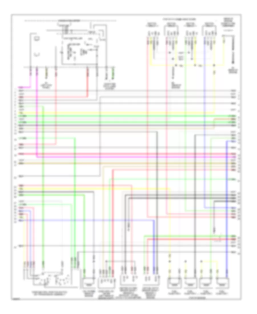
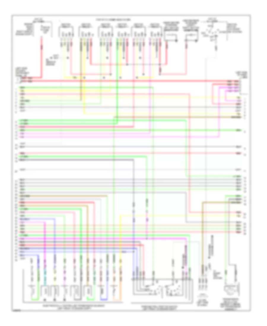
2.5L, Engine Performance Wiring Diagram (4 of 5) for Toyota RAV4 2009
 https://portal-diagnostov.com/license.html
Automotive Electricians Portal FZCO
Automotive Electricians Portal FZCO
https://portal-diagnostov.com/license.html
https://portal-diagnostov.com/license.html
Automotive Electricians Portal FZCO
Automotive Electricians Portal FZCOList of elements for 2.5L, Engine Performance Wiring Diagram (4 of 5) for Toyota RAV4 2009:
- (rear of engine) noise filter (ignition)
- (top of cylinder head cover)
- (top of engine)
- 5v ic
- 5v+b
- A/t oil temp ind
- A1a+
- A1a-
- Air fuel ratio sensor (bank 1 sensor 1) (rear of engine)
- B1 (rear of engine)
- B2 (rear of engine)
- Can controller
- Can i/f
- Combination meter
- Computer data lines system
- Cpu
- E1 (left kick panel)
- E2g
- Fuel injector 1
- Fuel injector 2
- Fuel injector 3
- Fuel injector 4
- Gnd
- Ha1a
- Heated oxygen sensor (bank 1 sensor 2) (exhaust, after catalytic converter)
- Ht1b
- I/f
- Igf
- Ignition coil 1
- Ignition coil 2
- Ignition coil 3
- Ignition coil 4
- Igt1
- Igt2
- Igt3
- Igt4
- Led driver
- Malfunction ind lamp
- Mass air flow meter (left rear of engine compt)
- Nca
- Ox1b
- Park/neutral position switch (on transmission assembly)
- Pnk
- Red
- Shift ind
- Tha
- Vsv (purge) (rear of engine)
2.5L, Engine Performance Wiring Diagram (5 of 5) for Toyota RAV4 2009
 https://portal-diagnostov.com/license.html
Automotive Electricians Portal FZCO
Automotive Electricians Portal FZCO
https://portal-diagnostov.com/license.html
https://portal-diagnostov.com/license.html
Automotive Electricians Portal FZCO
Automotive Electricians Portal FZCOList of elements for 2.5L, Engine Performance Wiring Diagram (5 of 5) for Toyota RAV4 2009:
- (left rear of engine) engine coolant temperature sensor
- (left rear of engine) intake air control valve actuator
- (rear of engine) b1
- (rear of engine) b2
- (rear of engine) vvt sensor (bank 1 exhaust side)
- (right rear of engine) vvt sensor (bank 1 intake side)
- A1a+
- A1a-
- B1 (rear of engine)
- B30
- Canister pressure sensor
- Canister pump module
- Crankshaft position sensor (front of engine)
- E01
- E02
- E2g
- Eia1
- Eknk
- Engine control module (left side of engine compt)
- Eo3
- Eppm
- Eta
- Etha
- Etho
- Ethw
- Ev1+
- Ev1-
- G2+
- G2-
- Gnd
- Iac1
- Igt1
- Igt2
- Igt3
- Igt4
- Knk1
- Knock control sensor (bank 1) (side of engine block)
- Leak detection pump
- Nc+
- Nc-
- Nca
- Ne+
- Ne-
- Nt+
- Nt-
- O1b-
- Oc1-
- Oe1-
- Out
- Ox1b
- Pnk
- Ppmp
- Red
- Skid control ecu w/ actuator (rear of engine compt)
- Sp1
- Th01
- Tha
- Throttle body assembly (rear of engine)
- Thw
- Transmission control switch (under center console)
- Transmission revolution sensor (counter gear) (on transmission assembly)
- Transmission revolution sensor (turbine) (on transmission assembly)
- Vc2
- Vce1
- Vcia
- Vcpp
- Vcta
- Vcv1
- Vdd
- Vent valve
- Vta
- Vta1
- Vta2
- Vve+
- Vve-
- Vvi+
- Vvi-
3.5L
3.5L, Engine Performance Wiring Diagram (1 of 5) for Toyota RAV4 2009
 https://portal-diagnostov.com/license.html
Automotive Electricians Portal FZCO
Automotive Electricians Portal FZCO
https://portal-diagnostov.com/license.html
https://portal-diagnostov.com/license.html
Automotive Electricians Portal FZCO
Automotive Electricians Portal FZCOList of elements for 3.5L, Engine Performance Wiring Diagram (1 of 5) for Toyota RAV4 2009:
- (left kick panel) e1
- (left side of dash) j/c a37
- +b2
- A/f fuse 20a
- A/f relay
- A1 (left front of engine compt)
- A15
- A2 (left front of engine compt)
- A35
- A38
- A50
- A78
- A79
- Accelerator pedal position sensor (left side of dash)
- Accr
- Am1
- Am2
- Am2-2 fuse 7.5a
- Anti-theft system
- B11
- B15
- B26
- B27
- B43
- Batt
- C/opn relay
- Canh
- Canl
- Ccs
- Com
- Computer data lines system
- Cooling fans system
- Cruise control system
- Defogger system
- E16
- E17
- Efi main fuse 20a
- Efi main relay
- Els1
- Els2
- Engine control module (left side of engine compt)
- Engine room j/b 1 (left side of engine compt)
- Engine switch (w/ smart key system)
- Epa
- Epa2
- Fpr
- Fuel pump resistor (left rear of engine compt)
- Gnd
- Hot at all times
- Hot in on or start
- Hot w/ t-lp relay power energized
- Ign fuse 7.5a
- Igsw
- Imi
- Imo
- Instrument panel j/b (left side of dash)
- J/b 3 (w/ smart key system) (left side of dash)
- J/c a35 & a38 (left side of dash)
- Lines system computer data
- Main body ecu (left side of dash)
- Mpmp
- Mrel
- Pnk
- Red
- Rfc
- Spd
- Ssw1
- Ssw2
- St1-
- Sta
- Starting/charging system
- Stop lamp switch (left side of dash)
- Stp
- Stsw
- Tach
- Tail fuse 10a
- Transmission control switch (under center console)
- Vcp2
- Vcpa
- Vpa
- Vpa2
- Vpmp
- W/ smart key system
3.5L, Engine Performance Wiring Diagram (2 of 5) for Toyota RAV4 2009
 https://portal-diagnostov.com/license.html
Automotive Electricians Portal FZCO
Automotive Electricians Portal FZCO
https://portal-diagnostov.com/license.html
https://portal-diagnostov.com/license.html
Automotive Electricians Portal FZCO
Automotive Electricians Portal FZCOList of elements for 3.5L, Engine Performance Wiring Diagram (2 of 5) for Toyota RAV4 2009:
- (left ''b'' pillar) k1
- (rear of engine) b3
- (rear of engine) b4
- +bm
- A1 (left front of engine compt)
- Alt
- B18
- B29
- B30
- Charging system starting/
- Dsl
- E01
- E02
- Efi 1 fuse 10a
- Efi 2 fuse 10a
- Engine control module (left side of engine compt)
- Engine room j/b 1 (left side of engine compt)
- Eo3
- Eo4
- Eo5
- Etcs fuse 10a
- F/pmp relay
- Fuel suction pump (fuel tank assembly)
- Gauge 1 fuse 10a
- Gauge 2 fuse 7.5a
- Ge01
- Ha1a
- Ha2a
- Hot at all times
- Hot in on or start
- Ht1b
- Ht2b
- Ig 2 fuse 15a
- Ig2 relay
- Igt1
- Igt2
- Igt3
- Igt4
- Igt5
- Igt6
- Instrument panel j/b (left side of dash)
- Left exhaust side camshaft timing oil control valve (front of engine)
- Left intake side camshaft timing oil control valve (front of engine)
- Oc2+
- Oc2-
- Oe2+
- Oe2-
- Pnk
- Red
- Sl1-
- Sl2+
- Sl2-
- Sl3+
- Sl3-
- Slt+
- Slt-
- Star
- Starting/ charging system
- Stop fuse 10a
3.5L, Engine Performance Wiring Diagram (3 of 5) for Toyota RAV4 2009
 https://portal-diagnostov.com/license.html
Automotive Electricians Portal FZCO
Automotive Electricians Portal FZCO
https://portal-diagnostov.com/license.html
https://portal-diagnostov.com/license.html
Automotive Electricians Portal FZCO
Automotive Electricians Portal FZCOList of elements for 3.5L, Engine Performance Wiring Diagram (3 of 5) for Toyota RAV4 2009:
- (center rear of engine compt) right ignition noise filter
- (left side of dash) instrument panel j/b
- (left side of dash) j/b 3
- (near center of engine) left ignition noise filter
- (top of cylinder head cover)
- A17
- A22
- A77
- Acc
- Am1
- B30
- B4 (rear of engine)
- B46
- Charging system starting/
- Dsl
- Ecu-b fuse 10a
- Electronically controlled transmission solenoid (left front of engine compt)
- Engine room r/b 2 (right side of engine compt)
- Gnd
- H12
- Hot at all times
- Igf
- Ignition coil 1
- Ignition coil 2
- Ignition coil 3
- Ignition coil 4
- Ignition coil 5
- Ignition coil 6
- Ignition switch (w/o smart key system)
- Igt1
- Igt2
- Igt3
- Igt4
- Igt5
- Igt6
- J/c a35 (left side of dash)
- Lock off
- Park/neutral position switch (left front of engine compt)
- Pnk
- Red
- Sl1+
- Sl1-
- Sl2+
- Sl2-
- Sl3+
- Sl3-
- Slt+
- Slt-
- St1
- Start
- Tho
- Transmission revolution sensor (turbine) (on transmission assembly)
- W/ smart key system
3.5L, Engine Performance Wiring Diagram (4 of 5) for Toyota RAV4 2009
 https://portal-diagnostov.com/license.html
Automotive Electricians Portal FZCO
Automotive Electricians Portal FZCO
https://portal-diagnostov.com/license.html
https://portal-diagnostov.com/license.html
Automotive Electricians Portal FZCO
Automotive Electricians Portal FZCOList of elements for 3.5L, Engine Performance Wiring Diagram (4 of 5) for Toyota RAV4 2009:
- (exhaust, after catalytic converter) heated oxygen sensor (bank 2 sensor 2)
- (left rear of engine compt) mass air flow meter
- (left rear of engine compt) vsv (air intake control)
- (rear of engine compt) skid control ecu w/ actuator
- (rear of engine) vsv (purge)
- (right rear of engine compt) vsv (acis)
- (top of engine)
- 5v ic
- A/t oil temp ind
- A1a+
- A1a-
- A2a+
- A2a-
- Air fuel ratio sensor (bank 1 sensor 1) (exhaust, before catalytic converter)
- Air fuel ratio sensor (bank 2 sensor 1) (rear of engine)
- Can controller
- Can i/f
- Combination meter
- Computer data lines system
- Cpu
- E1 (left kick panel)
- E2g
- Ex+
- Ex-
- Fuel injector 1
- Fuel injector 2
- Fuel injector 3
- Fuel injector 4
- Fuel injector 5
- Fuel injector 6
- Ha2a
- Ht1a
- Ht2b
- I/f
- Led driver
- Malfunction ind lamp
- Nca
- Ox2b
- Pnk
- Red
- Shift ind
- Sp1
- Tha
- Throttle body assembly (left rear of engine compt)
- Vc2
- Vta
- Vta2
- Vvt sensor (bank 2 exhaust side) (center of engine)
3.5L, Engine Performance Wiring Diagram (5 of 5) for Toyota RAV4 2009
 https://portal-diagnostov.com/license.html
Automotive Electricians Portal FZCO
Automotive Electricians Portal FZCO
https://portal-diagnostov.com/license.html
https://portal-diagnostov.com/license.html
Automotive Electricians Portal FZCO
Automotive Electricians Portal FZCOList of elements for 3.5L, Engine Performance Wiring Diagram (5 of 5) for Toyota RAV4 2009:
- (front of engine) right exhaust side camshaft timing oil control valve
- (front of engine) right intake side camshaft timing oil control valve
- (rear of engine) engine coolant temperature sensor
- A1a+
- A2a+
- A2a-
- Aicv
- B3 (rear of engine)
- B30
- Canister pressure sensor
- Canister pump module
- Crankshaft position sensor (front of engine)
- E2g
- Ekn2
- Eknk
- Engine control module (left side of engine compt)
- Eta
- Etha
- Ethw
- Ev1+
- Ev1-
- Ev2+
- Ev2-
- Ex+
- Ex-
- Ex1b
- Heated oxygen sensor (bank 1 sensor 2) (exhaust system)
- Ht1b
- Igf1
- Knk1
- Knk2
- Knock control sensor (bank 1) (side of engine block)
- Knock control sensor (bank 2) (side of engine block)
- Leak detection pump
- Me01
- Mgnd
- Mtrb
- Nca
- Ne+
- Ne-
- Nsw
- Nt+
- Nt-
- Oc1+
- Oc1-
- Oe1+
- Oe1-
- Ox1b
- Ox2b
- Pnk
- Ppmp
- Prg
- Red
- Sgnd
- Tha
- Tho1
- Thw
- Vc2
- Vcc
- Vcta
- Vcv1
- Vcv2
- Vent valve
- Vgnd
- Vlvb
- Vout
- Vta1
- Vta2
- Vv1+
- Vv1-
- Vv2+
- Vv2-
- Vvl+
- Vvl-
- Vvr+
- Vvr-
- Vvt sensor (bank 1 exhaust side) (right side of engine)
- Vvt sensor (bank 1 intake side) (front of engine)
- Vvt sensor (bank 2 intake side) (front of engine)

 Čeština
 Dansk
Dansk Deutsch
 Ελληνικά
 English
 English
 Español
 Suomi
Suomi Français
 Français
 עברית
עברית Hrvatski
 Magyar
 Italiano
 日本語
日本語 한국어
한국어 Nederlands
 Polski
 Português
 Português
 Română
 Русский
 Slovenčina
 Slovenščina
 Svenska
 中文 (中国)
