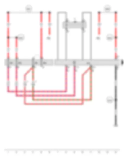
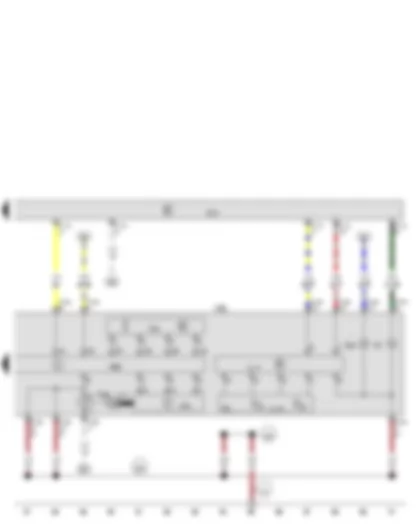
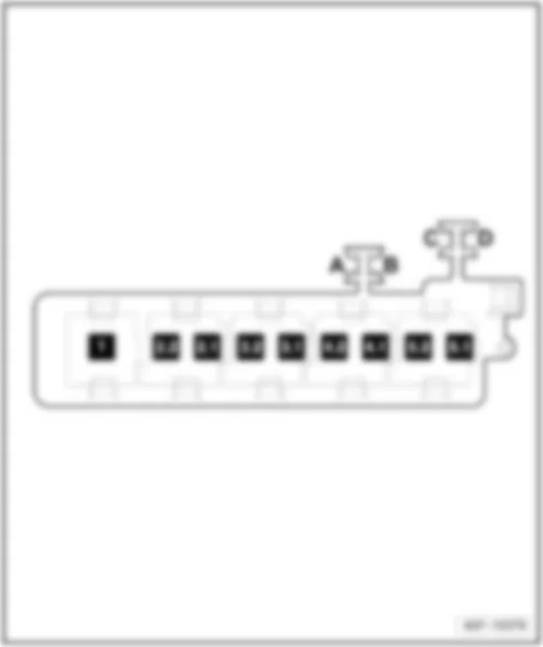
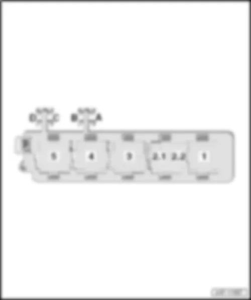
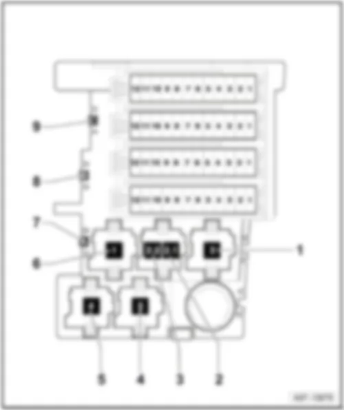
Wiring Diagram AUDI TT 2012 - Onboard supply control unit - Terminal 15 voltage supply relay 2
| J519 | Onboard supply control unit |
| J681 | Terminal 15 voltage supply relay 2 |
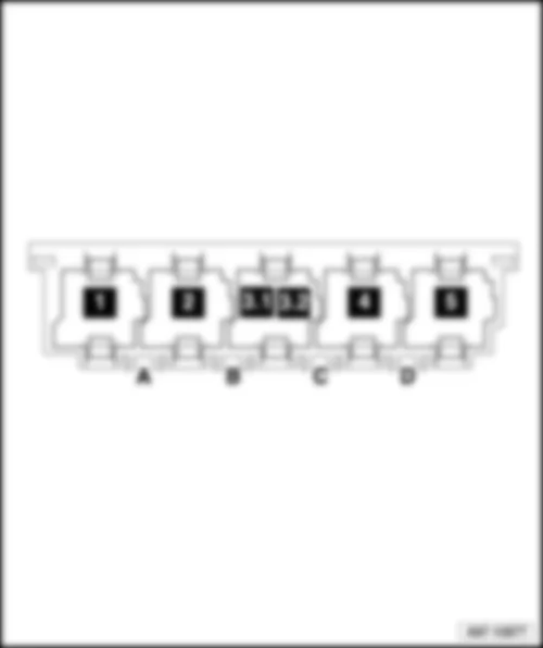
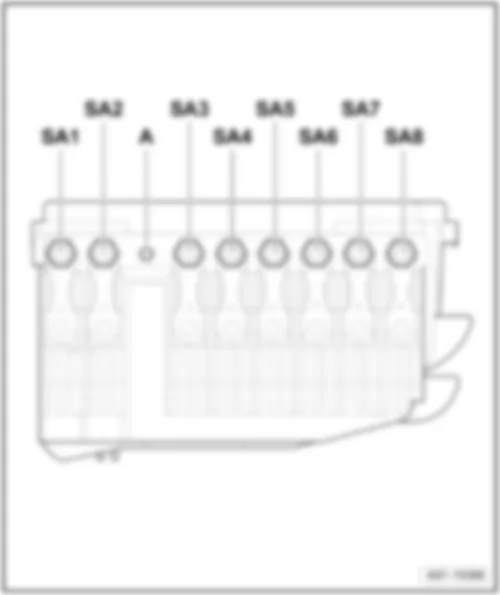
| SF1 | Fuse 1 in fuse holder F |
| SD2 | Fuse 2 on fuse holder D |
| SF2 | Fuse 2 in fuse holder F |
| SD3 | Fuse 3 on fuse holder D |
| SF7 | Fuse 7 in fuse holder F |
| SF8 | Fuse 8 in fuse holder F |
| T2t | 2-pin connector, black |
| T8h | 8-pin connector, black |
| T11b | 11-pin connector, black |
| T11c | 11-pin connector, brown |
| B163 | Positive connection 1 (15), in interior wiring harness |
| B299 | Positive connection 3 (30), in main wiring harness |
| B300 | Positive connection 4 (30), in main wiring harness |
| B301 | Positive connection 5 (30), in main wiring harness |
| B302 | Positive connection 6 (30), in main wiring harness |
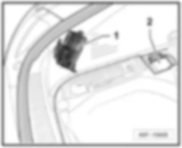
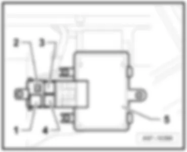
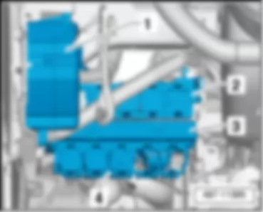
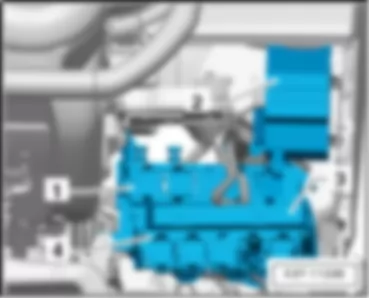
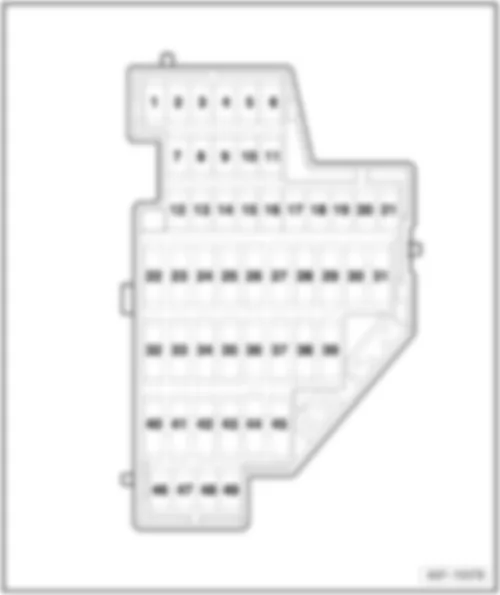
| * | Main fuse box, on battery on rear right in luggage compartment |
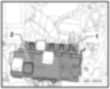
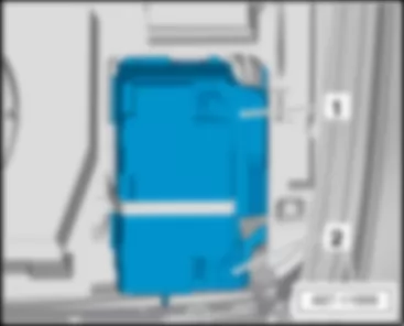
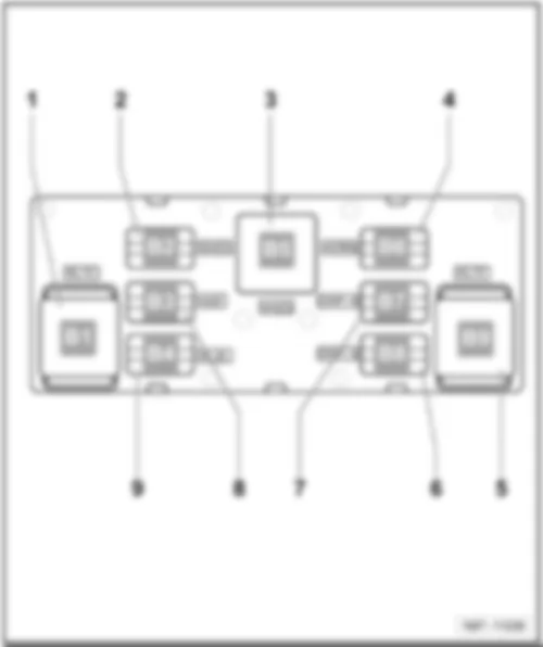
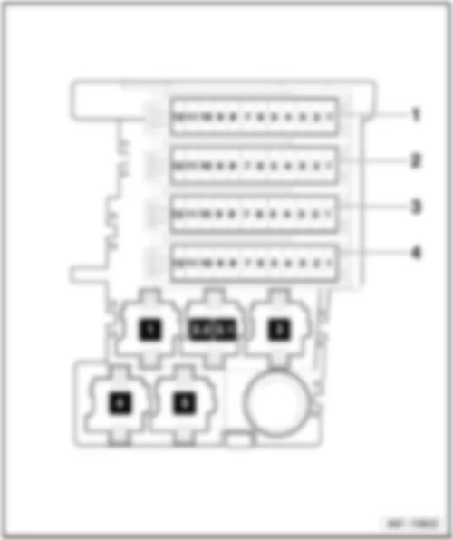
| *2 | Relay carrier on onboard supply control unit, on left under dash panel |
| *3 | Coupé |
| *4 | Roadster |
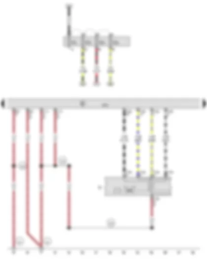
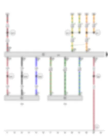
Wiring Diagram AUDI TT 2012 - Light switch - Onboard supply control unit
| E1 | Light switch |
| J519 | Onboard supply control unit |
| SC1 | Fuse 1 on fuse holder C |
| SC3 | Fuse 3 on fuse holder C |
| SC4 | Fuse 4 on fuse holder C |
| SC5 | Fuse 5 on fuse holder C |
| T6h | 6-pin connector |
| T8h | 8-pin connector, black |
| T10e | 10-pin connector, black |
| T11b | 11-pin connector, black |
| T11c | 11-pin connector, brown |
| T16a | 16-pin connector, black |
| 44 | Earth point, lower part of left A-pillar |
| 374 | Earth connection 9, in main wiring harness |
| 375 | Earth connection 10, in main wiring harness |
| 376 | Earth connection 11, in main wiring harness |
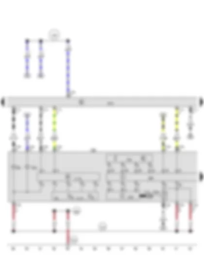
Wiring Diagram AUDI TT 2012 - Onboard supply control unit - Output module for left headlight - Left LED module for daytime running light and side light - Front left headlight
| J343 | Left gas discharge bulb control unit |
| J519 | Onboard supply control unit |
| J667 | Output module for left headlight |
| L13 | Left gas discharge (xenon) bulb |
| L174 | Left daytime running light bulb |
| L176 | Left LED module for daytime running light and side light |
| M1 | Left side light bulb |
| MX1 | Front left headlight |
| M5 | Front left turn signal bulb |
| M33 | Front left side marker bulb |
| T11b | 11-pin connector, black |
| T11c | 11-pin connector, brown |
| T12d | 12-pin connector, brown |
| T14a | 14-pin connector, black |
| V48 | Left headlight range control motor |
| V294 | Left dip beam screen motor |
| 366 | Earth connection 1, in main wiring harness |
| 372 | Earth connection 7, in main wiring harness |
| 672 | Earth point 2, on front of left longitudinal member |
| C65 | Positive connection 1, in side marker light wiring harness |
| * | Only for American markets |
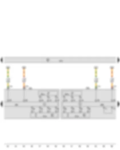
Wiring Diagram AUDI TT 2012 - Onboard supply control unit - Output module for left headlight - Output module for right headlight - Front left headlight - Front right headlight
| G474 | Left swivel module position sensor |
| G475 | Right swivel module position sensor |
| J519 | Onboard supply control unit |
| J667 | Output module for left headlight |
| J668 | Output module for right headlight |
| MX1 | Front left headlight |
| MX2 | Front right headlight |
| T14a | 14-pin connector, black |
| T14b | 14-pin connector, black |
| V318 | Left dynamic cornering light control motor |
| V319 | Right dynamic cornering light control motor |
| * | Data bus wire (CAN bus) |
Wiring Diagram AUDI TT 2012 - Onboard supply control unit - Output module for right headlight - Right LED module for daytime running light and side light - Front right headlight
| J344 | Right gas discharge bulb control unit |
| J519 | Onboard supply control unit |
| J668 | Output module for right headlight |
| L14 | Right gas discharge (xenon) bulb |
| L175 | Right daytime running light bulb |
| L177 | Right LED module for daytime running light and side light |
| MX2 | Front right headlight |
| M3 | Right side light bulb |
| M7 | Front right turn signal bulb |
| M34 | Front right side marker bulb |
| T11b | 11-pin connector, black |
| T11c | 11-pin connector, brown |
| T14b | 14-pin connector, black |
| V49 | Right headlight range control motor |
| V295 | Right dip beam screen motor |
| 43 | Earth point, lower part of right A-pillar |
| 389 | Earth connection 24, in main wiring harness |
| 390 | Earth connection 25, in main wiring harness |
| * | Only for American markets |
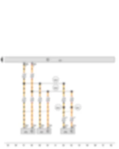
Wiring Diagram AUDI TT 2012 - Rear left vehicle level sender - Front left vehicle level sender - Headlight range control unit
| G76 | Rear left vehicle level sender |
| G78 | Front left vehicle level sender |
| J431 | Headlight range control unit |
| T4u | 4-pin connector, black |
| T4v | 4-pin connector, black |
| T26a | 26-pin connector, black |
| 44 | Earth point, lower part of left A-pillar |
| 384 | Earth connection 19, in main wiring harness |
| B278 | Positive connection 2 (15a) in main wiring harness |
| B467 | Connection 3, in main wiring harness |
| B468 | Connection 4, in main wiring harness |
| B469 | Connection 5, in main wiring harness |
| B470 | Connection 6, in main wiring harness |
| B471 | Connection 7, in main wiring harness |
| * | Only models with no electronic damping control |
| *2 | Data bus wire (CAN bus) |
Wiring Diagram AUDI TT 2012 - Headlight range control unit - Data bus diagnostic interface
| J250 | Electronically controlled damping control unit |
| J431 | Headlight range control unit |
| J527 | Steering column electronics control unit |
| J533 | Data bus diagnostic interface |
| T20c | 20-pin connector, black |
| T20d | 20-pin connector |
| T26a | 26-pin connector, black |
| T47a | 47-pin connector |
| B383 | Connection 1 (powertrain CAN bus, high), in main wiring harness |
| B384 | Connection 2 (powertrain CAN bus, high), in main wiring harness |
| B390 | Connection 1 (powertrain CAN bus, low), in main wiring harness |
| B391 | Connection 2 (powertrain CAN bus, low), in main wiring harness |
| * | Data bus wire (CAN bus) |
| *2 | Only models with electronic damping control |
AUDI TT 2012 Overview of control units
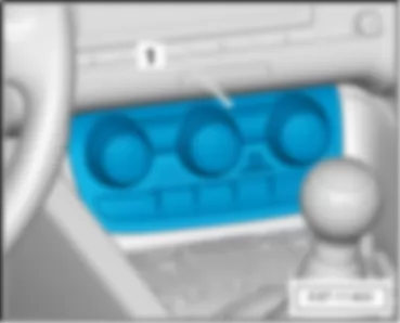
| Climatronic control unit -J255- |
| q | Components:-E230-, -G56-, -V42-, -E94-, -E95- |
| q | Location and connector assignment |
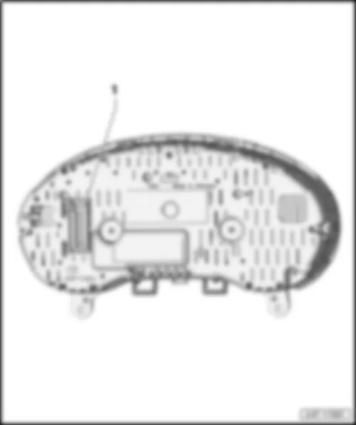
| Control unit in dash panel insert -J285- |
| q | Components:-G1-, -Y24-, -K3-, -K32-, -Y8-, -J362-, -K28- |
| q | Location and connector assignment |
| Front passenger door control unit -J387- |
| q | Components:-V148- |
| q | Location and connector assignment |
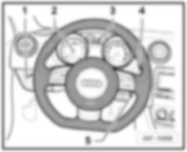
| Steering column electronics control unit -J527- |
| q | Components:-D-, -N376-, -G85-, -E45-, -E2-, -E4-, -E22-, -F138-, -H-, -N95-, -N250- |
| q | Location and connector assignment |
| Control unit for parking aid -J446- |
| q | Components -R78- |
| q | Location and connector assignment |
| q | is dropped from May 2009 |
| Digital sound package control unit -J525- |
| q | Components -R87- |
| q | Location |
| Driver door control unit -J386- |
| q | Components:-V147- |
| q | Location and connector assignment |
| q | Location and connector assignment from June 2009 |
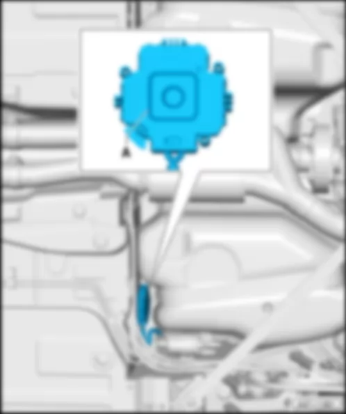
| Left gas discharge bulb control unit -J343-/right gas discharge light control unit -J344- |
| q | Components -J667-, -J668-, -V294-, -V295-, -V48-, -V49- |
| q | Location and connector assignment |
|
|
| A - | ABS control unit -J104- |
| . |
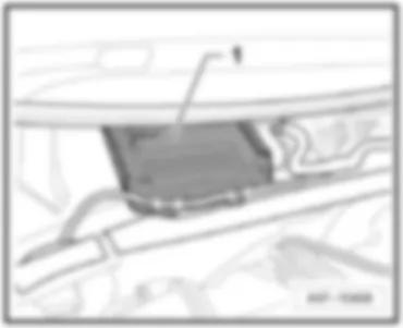
| Engine control unit -J623- |
| Fitting location |
|
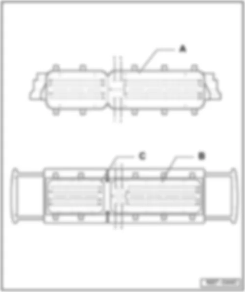
| A - | Engine control unit -J623- |
| C - | 60-pin connector -T60-, black, on wiring harness |
|
| A - | Engine control unit -J623- |
| C - | 40-pin connector -T40-, black, on wiring harness |
|
|
| C - | 12-pin connector -T12l-, black |
|
|
| A - | Convenience system central control unit -J393- |
| B - | Vacant |
| D - | 8-pin connector -T8g-, black, on wiring harness |
| F - | 18-pin connector -T18f-, black, on wiring harness |
|
Note
|
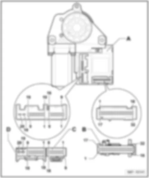
| A - | Driver door control unit -J386- |
| C - | 16-pin connector -T16f-, black, on wiring harness |
| D - | 20-pin connector -T20f-, black, on wiring harness |
|
Note
|
| A - | Front passenger door control unit -J387- |
| C - | 16-pin connector -T16g-, black, on wiring harness |
| D - | 20-pin connector -T20g-, black, on wiring harness |
|
|
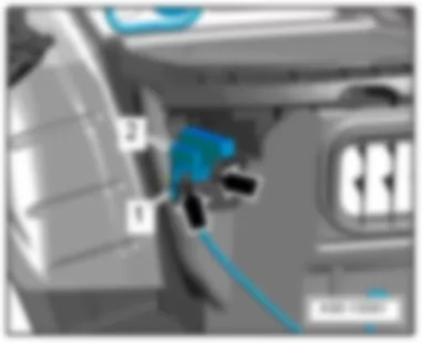
| 2 - | 10-pin connector -T10v-, black |
|
|
| A - | 47-pin connector -T47-, black |
|
| A - | Vacant |
| C - | 20-pin connector -T20c-, black, on wiring harness |
| E - | 12-pin connector -T12i- |
| G - | 10-pin connector -T10ag- |
| H - | 10-pin connector -T10ah- |
|
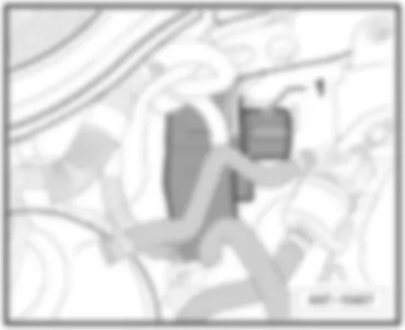
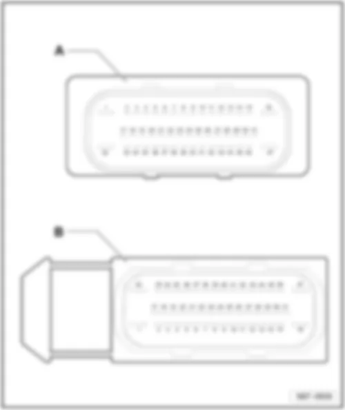
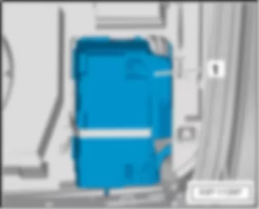
|
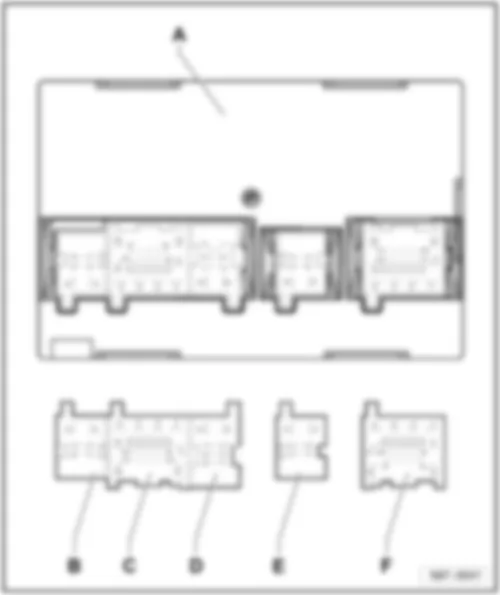
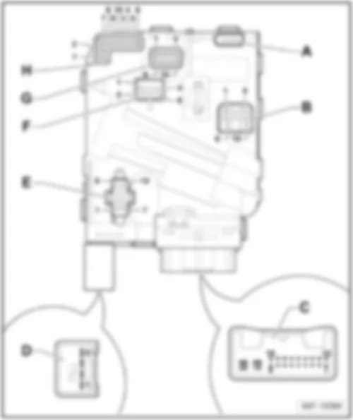
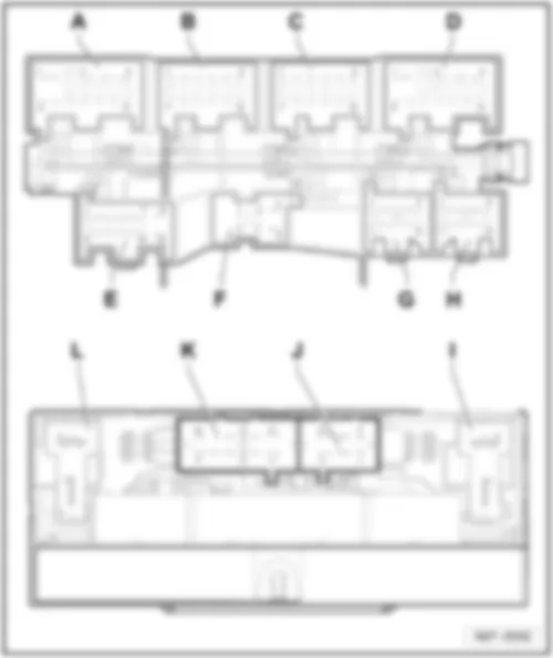
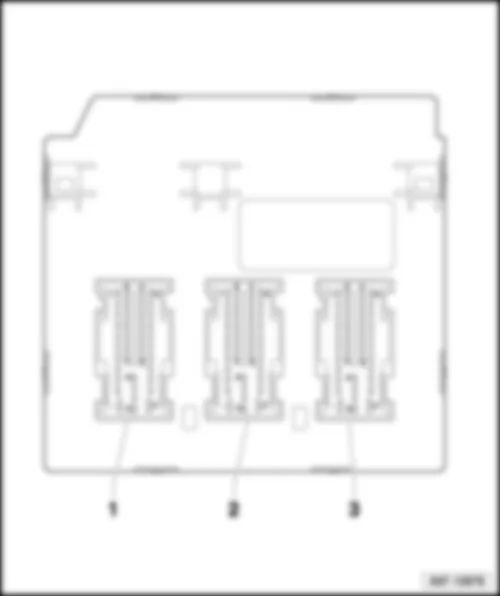
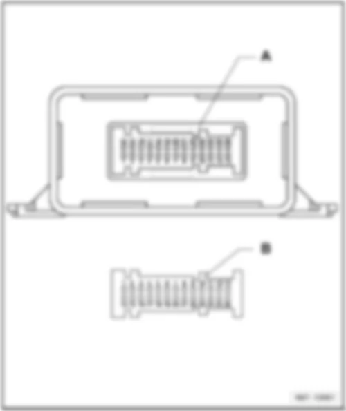
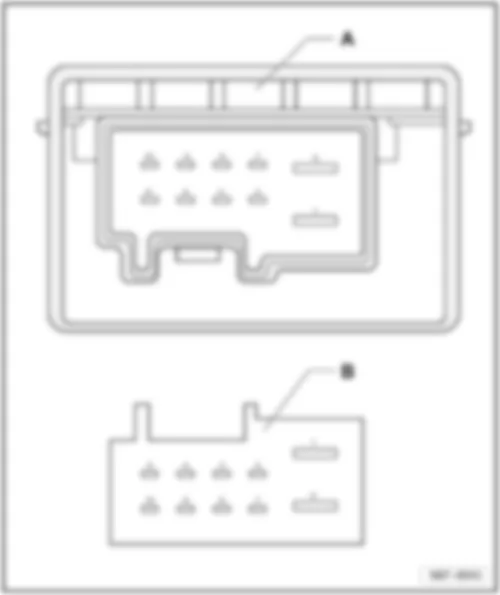
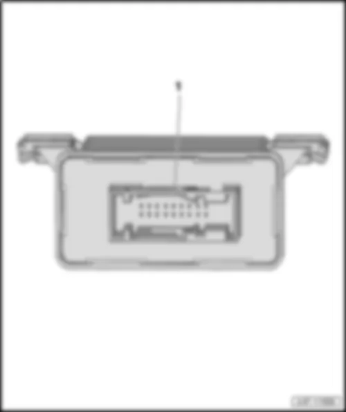
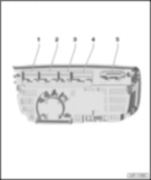
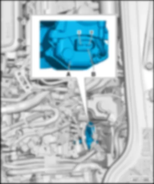
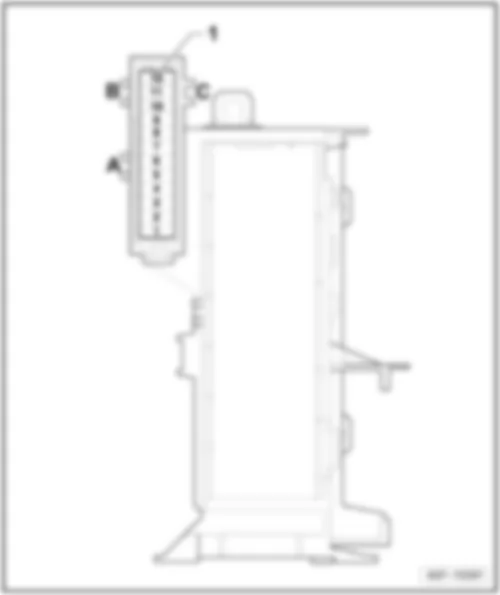
| B - | 12-pin connector -T12c-, black |
| D - | 11-pin connector -T11c-, brown |
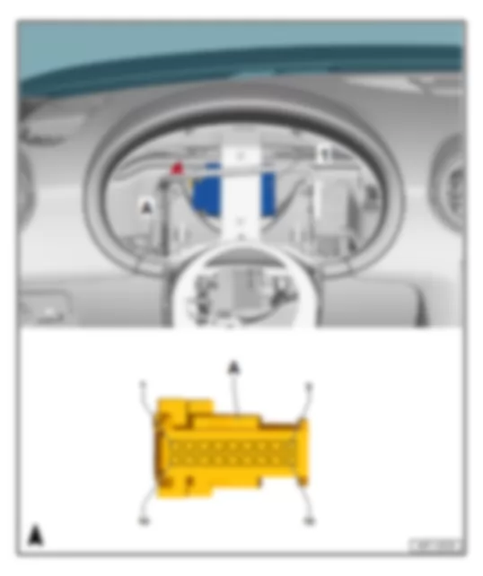
| F - | 8-pin connector -T8h-, black |
| J - | 6-pin, connector -T6h-, black |
| L - | 2-pin connector -T2t-, black |
|
|
|
| 2 - | 52-pin connector -T52b-, yellow |
| 3 - | 52-pin connector -T52c-, brown |
|
|
| 1 - | 32-pin connector -T32-, blue |
|
|
| 1 - | 20-pin connector -T20d-, black |
|
|
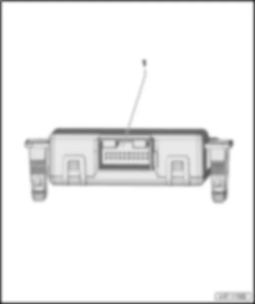
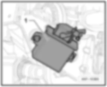
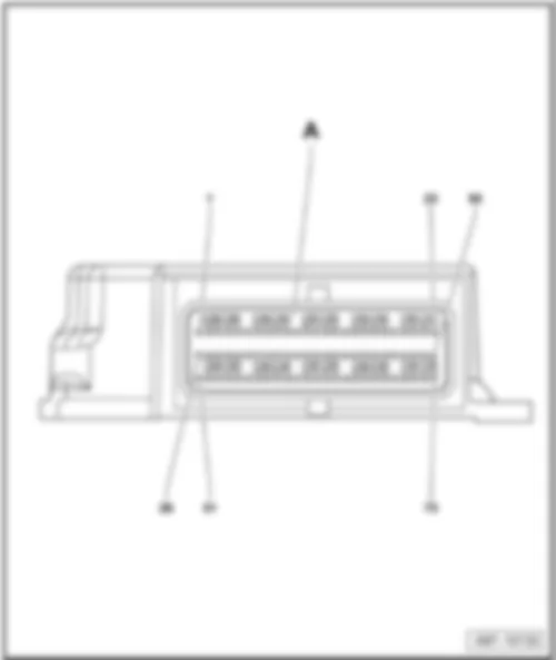
| A - | Headlight range control, control unit -J431- |
| B - | 26-pin connector -T26a-, black, on wiring harness |
|
|
| A - | 75-pin connector -T75-, yellow |
|
| A - | Fuel pump control unit -J538- |
|
| A - | Fuel pump control unit -J538- |
| B - | 10-pin connector -T10k-, black, on wiring harness |
|
|
| 1 - | 18-pin connector -T18c-, black |
|
|
| 2 - | 20-pin connector -T20k- |
| 4 - | 16-pin connector -T16c-, brown |
| 5 - | 3-pin connector -T3ae-, black |
|
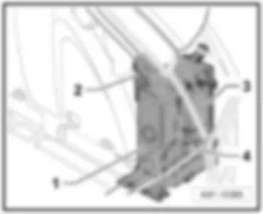
| 3 - | Wiper motor control unit -J400- |
| 5 - | 4-pin connector -T4-, black |
|
| 1 - | 4-pin connector -T4c-, black |
| 2 - | 4-pin connector -T4c-, black |
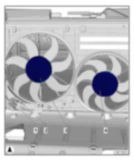
| 3 - | Radiator fan control unit -J293- |
| Radiator fan -V7- |
| 4 - | Radiator fan 2 -V177- |
|
| A - | Power steering control unit -J500- |
| B - | 2-pin connector -T2s-, black |
|
|
|
| 1 - | Tyre pressure monitor control unit -J502- |
| A - | 18-pin connector -T18c-, black |
|
| - T18c - | Designation | - T18c - | Designation | |
| 1 | 10 | |||
| 2 | 11 | |||
| 3 | Terminal 30 | 12 | ||
| 4 | 13 | |||
| 5 | Convenience CAN bus high | 14 | ||
| 6 | Convenience CAN bus low | 15 | ||
| 7 | 16 | Tyre pressure monitor button -E226-, in operating unit in front of centre console -E461- | ||
| 8 | 17 | |||
| 9 | Terminal 31 | 18 |
|
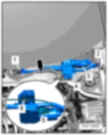
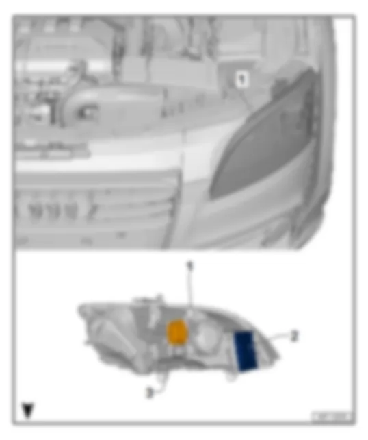
| 1 - | Bi-Xenon gas discharge headlights with cornering light, left and right |
| q | Output module for left headlight -J667-Output module for right headlight -J668-, in headlight housing |
| 2 - | Left gas discharge bulb control unit -J343-/right gas discharge light control unit -J344- |
| 14-pin connector -T14a-/14-pin connector -T14b-, black |
|
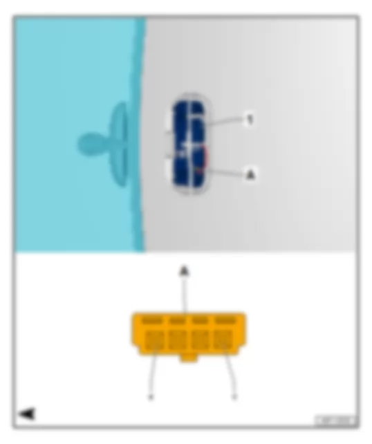
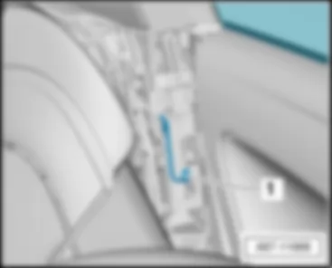
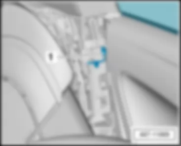
| 1 - | Front interior light -W1- with anti-theft alarm sensor -G578- |
| A - | 4-pin connector -T4p- |
|
| - T4p - (A) | Designation | - T4p - (A) | Designation | |
| 1 | 3 | onboard supply control unit -J519- | ||
| 2 | Terminal 31 | 4 | Terminal 30 |
|
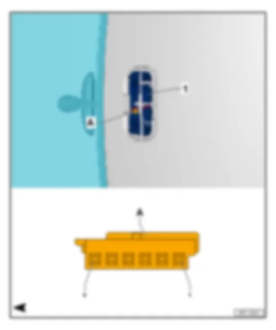
| 1 - | Front interior light -W1- |
| q | with front passenger side reading light -W13-, Driver side reading lamp -W19-, Driver side reading lamp button -E457-, Front passenger side reading lamp button -E458- |
| A - | 6-pin, connector -T6m-, brown |
|
| - T6m - (A) | Designation | - T6m - (A) | Designation | |
| 1 | Terminal 31 | 4 | onboard supply control unit -J519-, terminal 30a | |
| 2 | onboard supply control unit -J519- | 5 | Terminal 58s | |
| 3 | Automatic anti-dazzle interior mirror -Y7- | 6 | Terminal 30 |
|
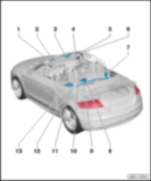
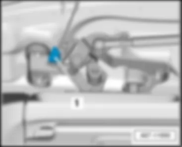
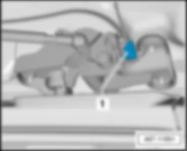
| Overview of convertible roof components |
| q | Location convertible roof latch open switch -F294- |
| 5 - | Convertible roof latch closed switch -F295-, right |
| q | Location |
| Right convertible top cover motor -V381-/right sender for convertible roof cover -G597- |
| q | Location |
| Left convertible top cover motor -V383-/left sender for convertible roof cover -G596- |
| q | Location |
|
|
|
|
|
|
|
|
|
|
|
|
|
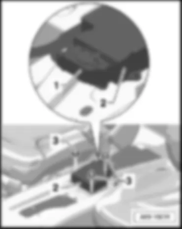
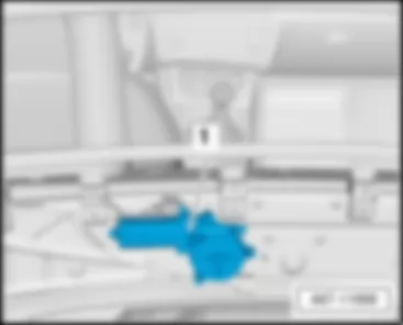
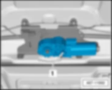
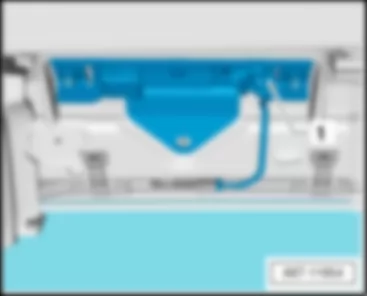
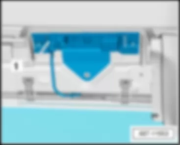
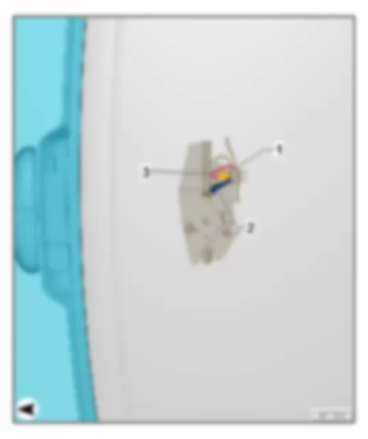
| 1 - | Convertible roof latch open switch -F294- |
| 2 - | Contact for convertible roof latch open switch -F294- |
| 3 - | Cable to 4-pin connector -T4w- |
|
 Deutsch
 English
 English
 Español
 Français
 Nederlands
 Русский

