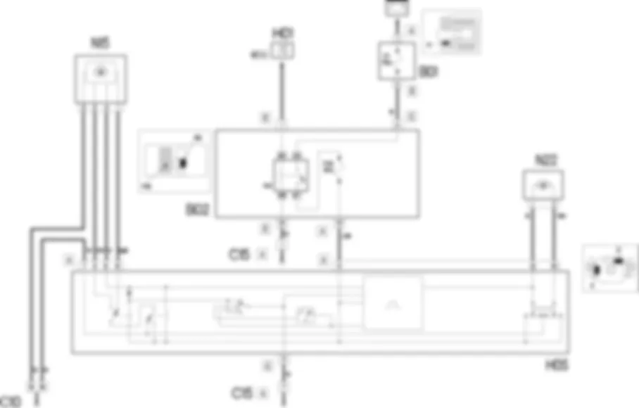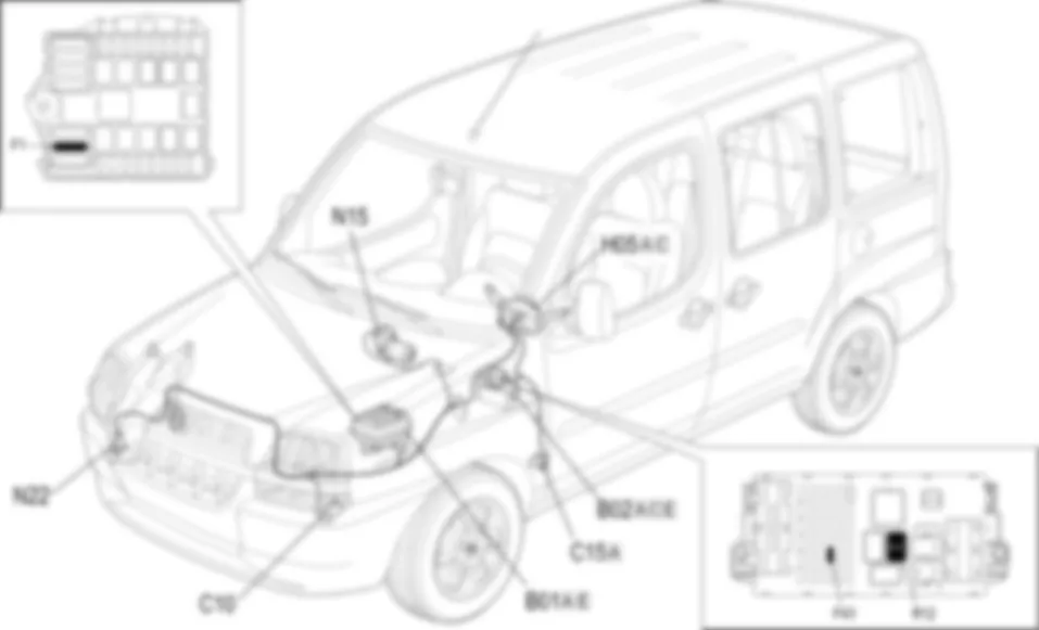

Wiring diagram - WINDSCREEN WASH/WIPE - Fiat DOBLO 1.9 JTD 8V da 12/03
COMPONENTS - WINDSCREEN WASH/WIPE - Fiat DOBLO 1.9 JTD 8V da 12/03
| Component code | Name | Assembly reference |
| B1 | Engine compartment junction unit | - |
| B1 | Engine compartment junction unit | |
| B1 | Engine compartment junction unit | |
| B2 | Junction unit under dashboard | - |
| B2 | Junction unit under dashboard | |
| C10 | Front left earth | - |
| C15 | Facia earth, driver''s side | - |
| H5 | Stalk unit | |
| H5 | Steering column switch unit | - |
| N15 | Windscreen wiper motor | |
| N22 | Windscreen/rearscreen electric washer pump motor |
Location of components - WINDSCREEN WASH/WIPE - Fiat DOBLO 1.9 JTD 8V da 12/03
COMPONENTS - WINDSCREEN WASH/WIPE - Fiat DOBLO 1.9 JTD 8V da 12/03
| Component code | Name | Assembly reference |
| B1 | Engine compartment junction unit | - |
| B1 | Engine compartment junction unit | |
| B1 | Engine compartment junction unit | |
| B2 | Junction unit under dashboard | - |
| B2 | Junction unit under dashboard | |
| C10 | Front left earth | - |
| C15 | Facia earth, driver''s side | - |
| H5 | Stalk unit | |
| H5 | Steering column switch unit | - |
| N15 | Windscreen wiper motor | |
| N22 | Windscreen/rearscreen electric washer pump motor |
Description - WINDSCREEN WASH/WIPE - Fiat DOBLO 1.9 JTD 8V da 12/03
The system operates with the ignition key turned ON.The windscreen wiper system is activated by the steering column switch unit lever on the right of the steering wheel.
Functional description - WINDSCREEN WASH/WIPE - Fiat DOBLO 1.9 JTD 8V da 12/03
The windscreen wiper switch on the steering column switch unit H05 makes it possible to select the different windscreen wash/wipe operating modes.The supply for the steering column switch unit H05 arrives at pin 11 of connector A via the outlet at pin 10 connector A of the junction unit under the dashboard B02 .Inside the junction unit B02 this line comes from the relay R12 via a line protected by fuse F43 . The supply at the relay arrives from the line protected by fuse F1 housed in the junction unit B01 from pin A connector C of the junction unit under the dashboard B02 .The operation of the relay R12 is determined by the supply line controlled by the ignition (INT/A) entering the junction unit under the dashboard B02 at pin 1 connector E.
 Deutsch
 English
 English
 Español
 Français
 Nederlands
 Русский

