TRANSMISSION
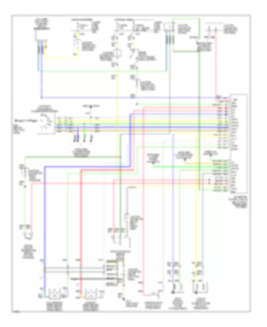
A/T Wiring Diagram for Acura 3.5RL 1996
List of elements for A/T Wiring Diagram for Acura 3.5RL 1996:
- (1996-98) (1999)
- (below front passenger's footrest)
- (in transmission)
- (on lower right front on engine) vehicle speed sensor
- (on side of transmission) a/t gear position switch
- Atp 1
- Atp 2
- Atp d3
- Atp d4
- Atp pn
- Atp r
- B13
- Back-up lamps
- Bksw
- Brake switch (top of brake pedal support)
- C301
- C307
- C404
- Countershaft speed sensor (right side of transmission)
- D4 ind
- Ect
- Engine coolant temperature sensor (top left of engine)
- Fuse 13 7.5a
- Fuse 39 15a 20a
- Fuse 56 7.5a
- G110 (left front of engine)
- G203 (behind right kick panel)
- Hot at all times
- Hot in on or start
- Ilu
- Instrument cluster system (d4 indicator)
- Instrument cluster system (gear position indicators)
- Instrument cluster system (p/n output)
- Interlock control unit
- Junction connector (above right kick panel)
- Junction connector (below right side of dash)
- Junction connector (right front of engine)
- Junction connector (right side of dash)
- Lc a
- Lc b
- Linear solenoid (on bottom of transmission)
- Lock-up control solenoid valves (on top of transmission)
- Ls +
- Ls-
- Mainshaft speed sensor (right side of transmission)
- Nca
- Ncsg
- Nmsg
- Powertrain control module
- Red
- Scs
- Service check connector (below right side of dash)
- Sg2
- Sh a
- Sh b
- Shift control solenoid valves
- Throttle position sensor (top of engine)
- Tps
- Under- dash fuse/ relay box
- Under- hood fuse/ relay box
- Vbu
- Vcc2
- Vss
 English