TRANSMISSION
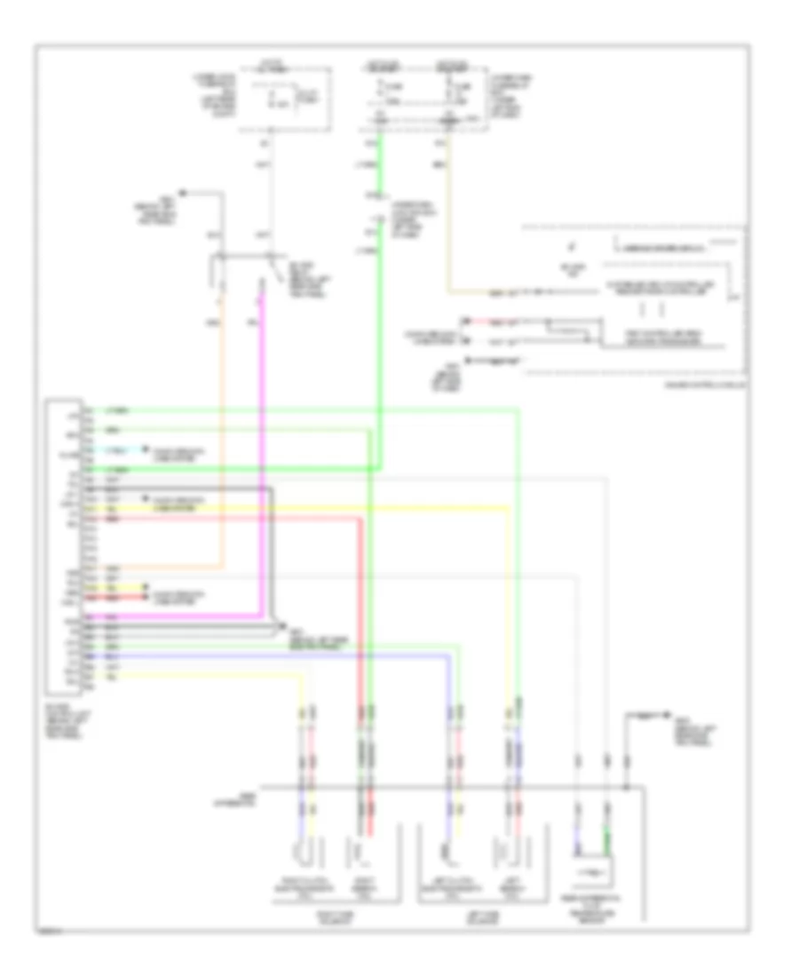
A/T Wiring Diagram (1 of 2) for Acura RDX 2008

List of elements for A/T Wiring Diagram (1 of 2) for Acura RDX 2008:
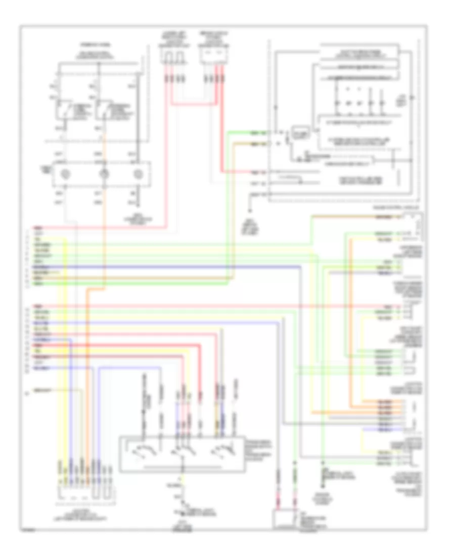
A/T Wiring Diagram (2 of 2) for Acura RDX 2008
List of elements for A/T Wiring Diagram (2 of 2) for Acura RDX 2008:
Rear Differential Lock Wiring Diagram for Acura RDX 2008
List of elements for Rear Differential Lock Wiring Diagram for Acura RDX 2008: