TRANSMISSION
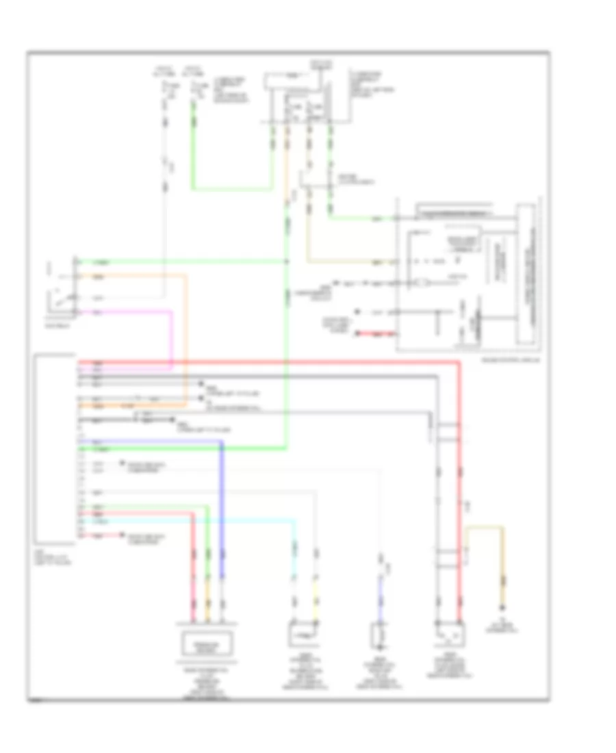
A/T Wiring Diagram (1 of 3) for Acura RDX 2013

List of elements for A/T Wiring Diagram (1 of 3) for Acura RDX 2013:
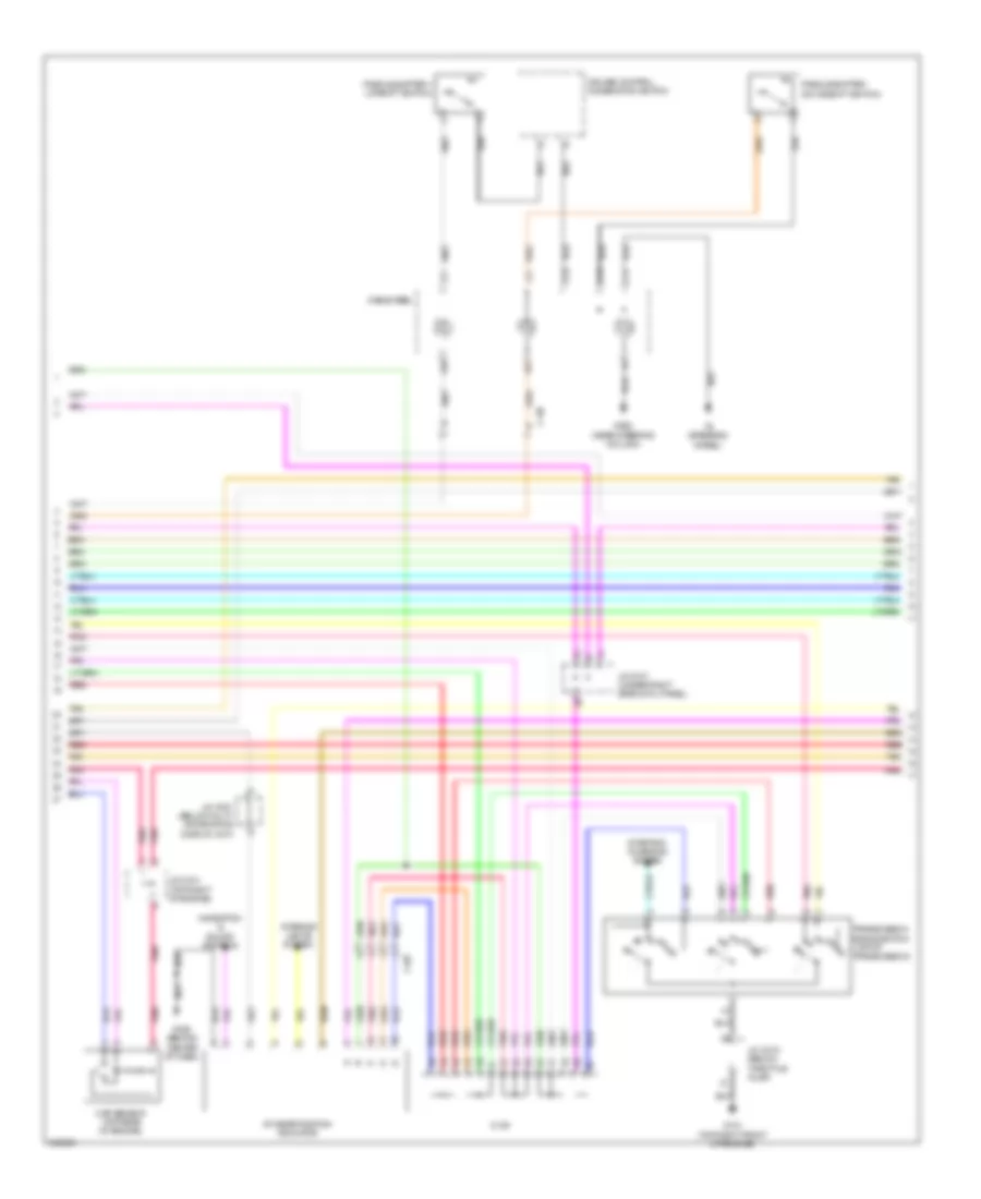
A/T Wiring Diagram (2 of 3) for Acura RDX 2013
List of elements for A/T Wiring Diagram (2 of 3) for Acura RDX 2013:
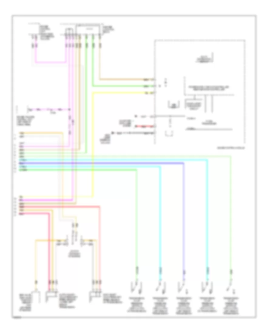
A/T Wiring Diagram (3 of 3) for Acura RDX 2013
List of elements for A/T Wiring Diagram (3 of 3) for Acura RDX 2013:
AWD Wiring Diagram for Acura RDX 2013
List of elements for AWD Wiring Diagram for Acura RDX 2013: