TRANSMISSION
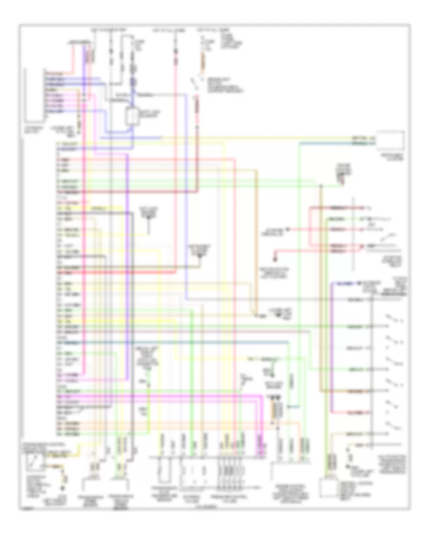
A/T Wiring Diagram for Audi A6 1999
List of elements for A/T Wiring Diagram for Audi A6 1999:
- (below left side of dash) data link connector (dlc)
- (lower left "a" pillar)
- (not used)
- 01l trans jc
- 11-12
- 13- fold relay panel (behind left side of dash)
- 231a
- 38-39
- 48-50
- 50a
- 50z
- 56-84
- Anti-lock brakes
- Anti-lock brakes system
- Brakelight switch (on brake pedal support bracket)
- Central locking control module (below driver's seat)
- Cruise control system
- Engine control module (ecm) (in electronic box, left side of fresh air plenum)
- Exterior lights system
- Fuse 10a
- Fuse 15a
- Fuse panel (left side of dash)
- G104 (left side of eng compt)
- G900
- G900 (lower left "a" pillar)
- Hot at all times
- Hot in on or start
- Ignition switch terminal 50 (hot in start)
- Instrument cluster
- Instrument cluster system
- Kickdown switch (on firewall, part of throttle cable)
- Multifunction transmission range switch (left side of transmission)
- Pressure control valves
- Red
- Shift lock solenoid
- Solenoid valves
- Starter terminal 50
- Starting interlock relay
- System
- Tiptronic switch
- Transmission control module (tcm) (under right front seat)
- Transmission fluid temperature sensor
- Transmission speed sensor
- Transmission vehicle speed sensor
- Valve body
 English