TRANSMISSION
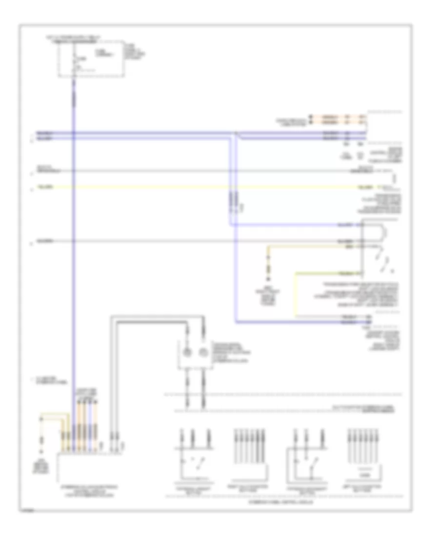
A/T Wiring Diagram, 8 Speed A/T (1 of 2) for Audi A6 Premium Plus Quattro 2013

List of elements for A/T Wiring Diagram, 8 Speed A/T (1 of 2) for Audi A6 Premium Plus Quattro 2013:
- 12a
- 13a
- Automatic transmission pressure regulating valve 1
- Automatic transmission pressure regulating valve 2
- Automatic transmission pressure regulating valve 3
- Automatic transmission pressure regulating valve 4
- Automatic transmission pressure regulating valve 5
- Automatic transmission pressure regulating valve 6
- Automatic transmission pressure regulating valve 7
- Computer data lines system
- Drive position sensor
- Fuse 15a
- Fuse 5a
- Fuse carrier 4
- Fuse panel a (in left plenum chamber e-box)
- Fuse panel f (right rear of luggage compt)
- G645
- G687 (right front side of center tunnel)
- Hot at all times
- Selector lever sensor system control module (base of shift lever assembly)
- Solenoid valve 1
- T17b
- T32a
- Transmission control module (tcm) (under transmission oil pan)
- Transmission fluid temperature sensor
- Transmission input speed sensor
- Transmission output speed sensor
- Vehicle electrical system control module (left end of dash)
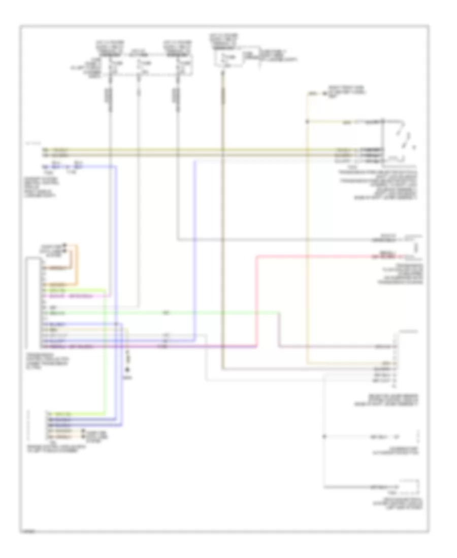
A/T Wiring Diagram, 8 Speed A/T (2 of 2) for Audi A6 Premium Plus Quattro 2013
List of elements for A/T Wiring Diagram, 8 Speed A/T (2 of 2) for Audi A6 Premium Plus Quattro 2013:
- 2.0l turbo
- 3.0l sc
- Air bag spiral spring/return spring w/ slip ring (top of steering column)
- Comfort system central control module (right side of luggage compt)
- Computer data lines system
- Engine control module (in left plenum chamber)
- Fuse 5a
- Fuse carrier 1
- Fuse panel c (right end of dash)
- G45 (behind center of dash)
- G687 (right front side of center tunnel)
- Left multi-function buttons
- Mode
- Multi-function steering wheel control module
- Nca
- Right multi-function buttons
- Steering column electronic control module (top of steering column)
- Steering wheel
- Steering wheel control module
- T12v
- T16e
- T17b
- T32g
- T94
- Tiptronic downshift button
- Tiptronic upshift button
- Transmission fluid cooling valve (if equipped) (on subframe or on transmission housing)
- Transmission park selector switch & shift lock solenoid (transmission park selector switch: integral to shift lock solenoid assembly) (shift lock solenoid: base of shift lever assembly)
- W/ heated
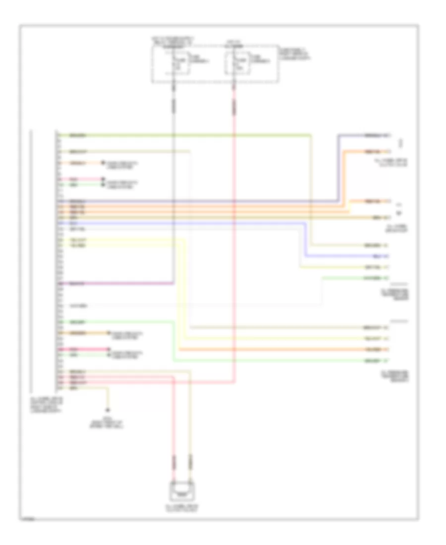
A/T Wiring Diagram, CVT for Audi A6 Premium Plus Quattro 2013
List of elements for A/T Wiring Diagram, CVT for Audi A6 Premium Plus Quattro 2013:
- (right front side of center tunnel) g687
- 12a
- 13a
- Access/start authorization button
- Comfort system central control module (right side of luggage compt)
- Computer data lines system
- Engine control module (ecm) (in left plenum chamber)
- Fuse 15a
- Fuse 5a
- Fuse carrier
- Fuse panel a (in left plenum chamber e-box)
- Fuse panel f (right rear of luggage compt)
- G645
- Hot at all times
- Nca
- Selector lever sensor system control module (base of shift lever assembly)
- T17b
- T32a
- T32g
- T4ca
- T94
- Transmission control module (tcm) (under transmission oil pan)
- Transmission fluid cooling valve (if equipped) (on subframe or on transmission housing)
- Transmission park selector switch & shift lock solenoid (transmission park selector switch: integral to shift lock solenoid assembly) (shift lock solenoid: base of shift lever assembly)
- Vehicle electrical system control module (left end of dash)
AWD Wiring Diagram for Audi A6 Premium Plus Quattro 2013
List of elements for AWD Wiring Diagram for Audi A6 Premium Plus Quattro 2013:
- 10a
- All wheel drive clutch valve
- All wheel drive clutch valve 2
- All wheel drive control module (right side of luggage compt)
- All wheel drive pump
- Computer data lines system
- Fuse 35a
- Fuse 5a
- Fuse carrier 4
- Fuse carrier 5
- Fuse panel f (right rear of luggage compt)
- G744 (right front of spare tire well)
- Hot at all times
- Oil pressure/ temperature sensor
- Oil pressure/ temperature sensor 2
- Pnk