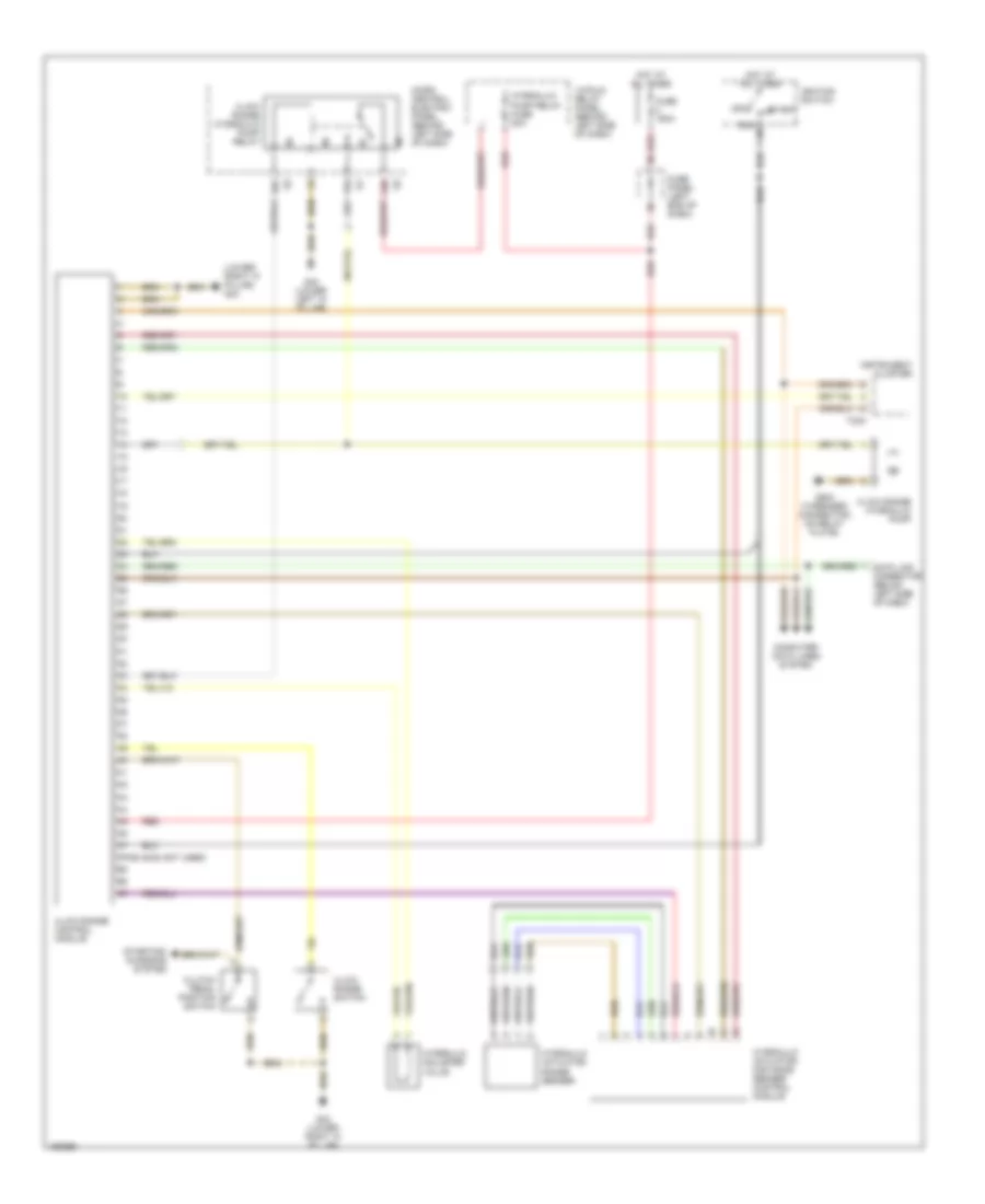
TRANSMISSION
A/T Wiring Diagram, with O1L for Audi allroad Quattro 2005

List of elements for A/T Wiring Diagram, with O1L for Audi allroad Quattro 2005:
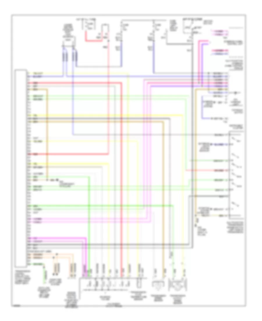
A/T Wiring Diagram, with O1V for Audi allroad Quattro 2005
List of elements for A/T Wiring Diagram, with O1V for Audi allroad Quattro 2005:
M/T Wiring Diagram, with Low Range Control Module for Audi allroad Quattro 2005
List of elements for M/T Wiring Diagram, with Low Range Control Module for Audi allroad Quattro 2005: