TRANSMISSION
A/T Wiring Diagram, with Direct Shift for Audi S5 Quattro 2008

List of elements for A/T Wiring Diagram, with Direct Shift for Audi S5 Quattro 2008:
- 10a
- Access/start authorization button
- Comfort system central control module (right rear of luggage compt)
- Computer data lines system
- Engine controls system
- Fuse 15a
- Fuse 5a
- G12 (left rear of engine compt)
- G688 (right side of center tunnel)
- Relay/fuse carrier e box sb (in left plenum chamber e-box)
- Selector lever sensor system control module
- Transmission control module (under transmission control panel)
- Transmission park selector switch & shift lock solenoid
- Vehicle electrical system control module (on relay & fuse panel)
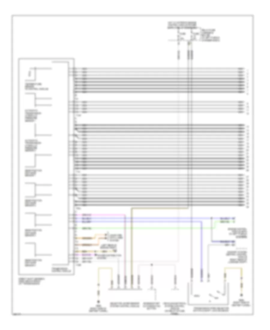
A/T Wiring Diagram, without Direct Shift (1 of 2) for Audi S5 Quattro 2008
List of elements for A/T Wiring Diagram, without Direct Shift (1 of 2) for Audi S5 Quattro 2008:
- (left rear of engine compt) g12
- 10a
- Access/start authorization button
- Automatic transmission hydraulic pressure sensor 1
- Automatic transmission hydraulic pressure sensor 2
- Comfort system central control module (right rear of luggage compt)
- Computer data lines system
- Direct shift gearbox (dsg) mechatronic (at transmission)
- Engine control module (ecm) (in left plenum chamber)
- Fuse 15a
- Fuse 5a
- G688 (right side of center tunnel)
- Gear position distance sensor 1
- Gear position distance sensor 2
- Gear position distance sensor 3
- Gear position distance sensor 4
- Nca
- Nca nca
- Power distribution system
- Relay/fuse carrier e box sb (in left plenum chamber e-box)
- Selector lever sensor system control module
- T14h
- T14i
- T16r
- T8al
- Temperature sensor (in control module)
- Transmission control module
- Transmission park selector switch & shift lock solenoid
- Vehicle electrical system control module (on relay & fuse panel)
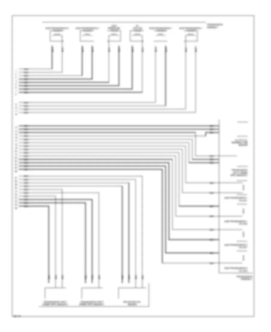
A/T Wiring Diagram, without Direct Shift (2 of 2) for Audi S5 Quattro 2008
List of elements for A/T Wiring Diagram, without Direct Shift (2 of 2) for Audi S5 Quattro 2008:
- Clutch oil temperature sensor
- Drive position sensor
- Main pressure valve
- Nca
- Nca nca
- Oil cooling valve
- Sub-transmission 1 valve 1
- Sub-transmission 1 valve 2
- Sub-transmission 1 valve 3
- Sub-transmission 1 valve 4
- Sub-transmission 2 valve 1
- Sub-transmission 2 valve 2
- Sub-transmission 2 valve 3
- Sub-transmission 2 valve 4
- Transmission assembly
- Transmission input speed (rpm) sensor 1
- Transmission input speed (rpm) sensor 2
- Transmission input speed (rpm) sensor 3
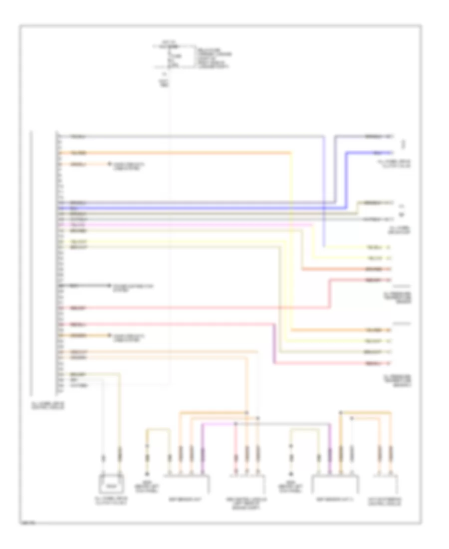
AWD Wiring Diagram for Audi S5 Quattro 2008
List of elements for AWD Wiring Diagram for Audi S5 Quattro 2008:
- Abs control module (left rear of engine compt)
- Active steering
- All wheel drive clutch valve
- All wheel drive clutch valve 2
- All wheel drive control module
- All wheel drive pump
- Computer data lines system
- Control module
- Esp sensor unit
- Esp sensor unit 2
- Fuse 35a
- G639 (behind left kick panel)
- Hot at all times
- Oil pressure/ temperature sensor
- Oil pressure/ temperature sensor 2
- Power distribution system
- Red
- Relay/fuse carrier luggage compt sf (right side of luggage compt)