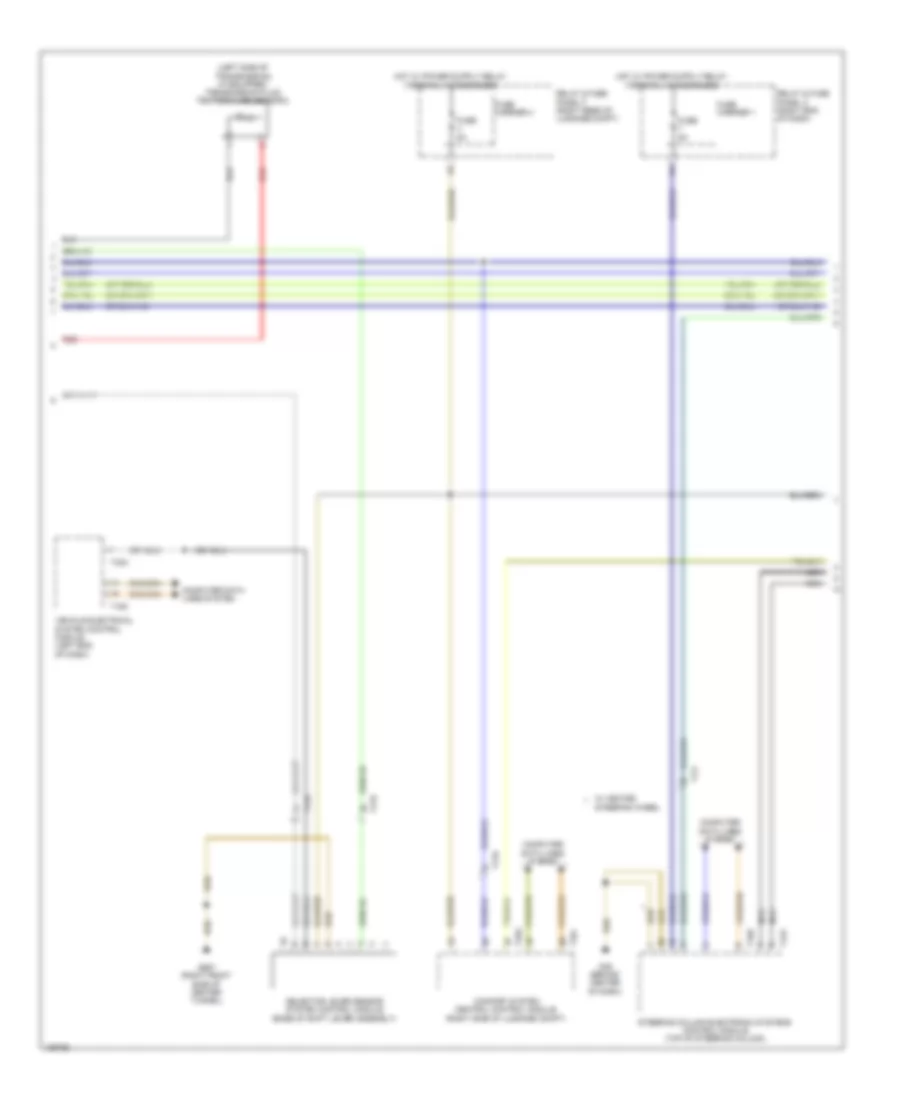
TRANSMISSION
A/T Wiring Diagram (1 of 3) for Audi S6 2014

List of elements for A/T Wiring Diagram (1 of 3) for Audi S6 2014:
- 12a
- 13a
- Automatic transmission hydraulic pressure sensor 1
- Automatic transmission hydraulic pressure sensor 2
- Clutch oil temperature sensor
- Computer data lines system
- Cooling oil valve
- Drive position sensor
- Dsg transmission mechatronic
- Fuse 15a (or 10a)
- Fuse 5a
- G645 (near engine control module on firewall)
- Gear position distance sensor 1
- Gear position distance sensor 2
- Gear position distance sensor 3
- Gear position distance sensor 4
- Hot at all times
- Main pressure valve
- Red
- Relay & fuse panel a (in left plenum chamber e-box)
- Sub-transmission 1 valve 1
- Sub-transmission 1 valve 2
- Sub-transmission 1 valve 3
- Sub-transmission 1 valve 4
- Sub-transmission 2 valve 1
- Sub-transmission 2 valve 2
- Sub-transmission 2 valve 3
- Sub-transmission 2 valve 4
- Temperature sensor (in control module)
- Transmission control module
- Transmission input speed sensor 1
- Transmission input speed sensor 2
- Transmission input speed sensor 3
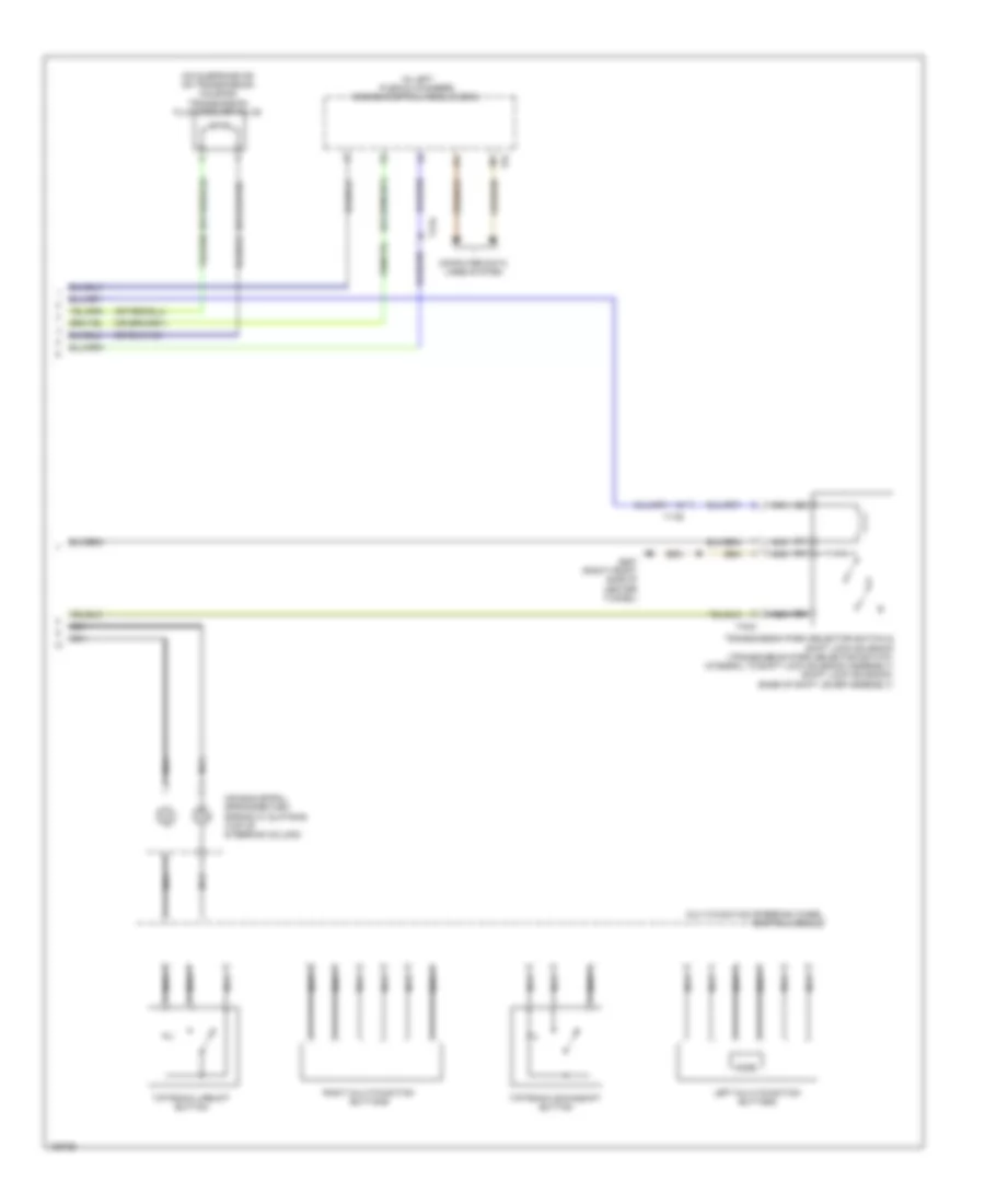
A/T Wiring Diagram (2 of 3) for Audi S6 2014
List of elements for A/T Wiring Diagram (2 of 3) for Audi S6 2014:
- (left side of transmission) (if equipped) transmission fluid temperature sensor 2
- Comfort system central control module (right side of luggage compt)
- Computer data lines system
- Fuse 5a
- Fuse carrier 1
- Fuse carrier 4
- G45 (behind center of dash)
- G687 (right front side of center tunnel)
- Nca
- Red
- Relay & fuse panel c (right end of dash)
- Relay & fuse panel f (right rear of luggage compt)
- Selector lever sensor system control module (base of shift lever assembly)
- Steering column electronic systems control module (top of steering column)
- Steering wheel
- T12v
- T16c
- T16e
- T17b
- T17i
- T32a
- T32g
- T32i
- Vehicle electrical system control module (left end of dash)
- W/ heated
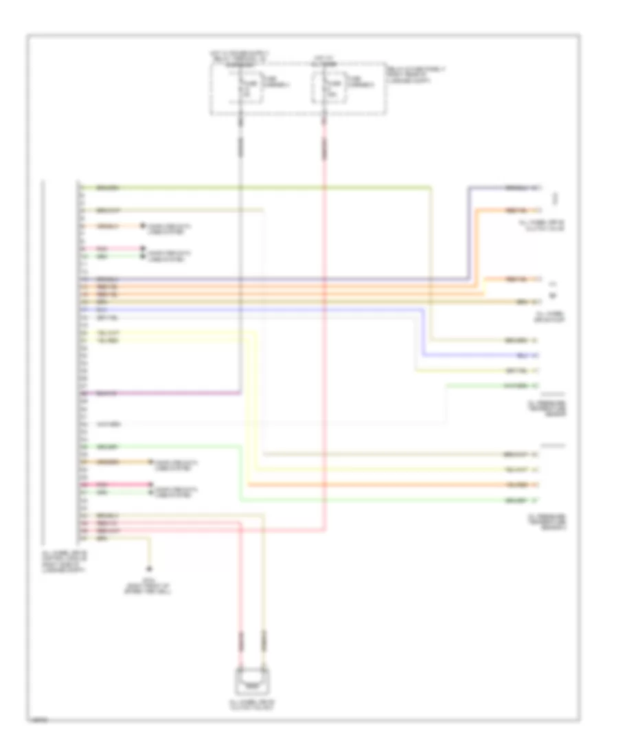
A/T Wiring Diagram (3 of 3) for Audi S6 2014
List of elements for A/T Wiring Diagram (3 of 3) for Audi S6 2014:
- (in left plenum chamber) engine control module (ecm)
- (on subframe or on transmission housing) transmission fluid cooling valve
- Air bag spiral spring/return spring w/ slip ring (top of steering column)
- Computer data lines system
- G687 (right front side of center tunnel)
- Left multi-function buttons
- Mode
- Multi-function steering wheel control module
- Nca
- Right multi-function buttons
- T17b
- T4ca
- T91
- Tiptronic downshift button
- Tiptronic upshift button
- Transmission park selector switch & shift lock solenoid (transmission park selector switch: integral to shift lock solenoid assembly) (shift lock solenoid: base of shift lever assembly)
AWD Wiring Diagram for Audi S6 2014
List of elements for AWD Wiring Diagram for Audi S6 2014:
- 10a
- All wheel drive clutch valve
- All wheel drive clutch valve 2
- All wheel drive control module (right side of luggage compt)
- All wheel drive pump
- Computer data lines system
- Fuse 35a
- Fuse 5a
- Fuse carrier 4
- Fuse carrier 5
- G744 (right front of spare tire well)
- Hot at all times
- Oil pressure/ temperature sensor
- Oil pressure/ temperature sensor 2
- Pnk
- Relay & fuse panel f (right rear of luggage compt)