TRANSMISSION
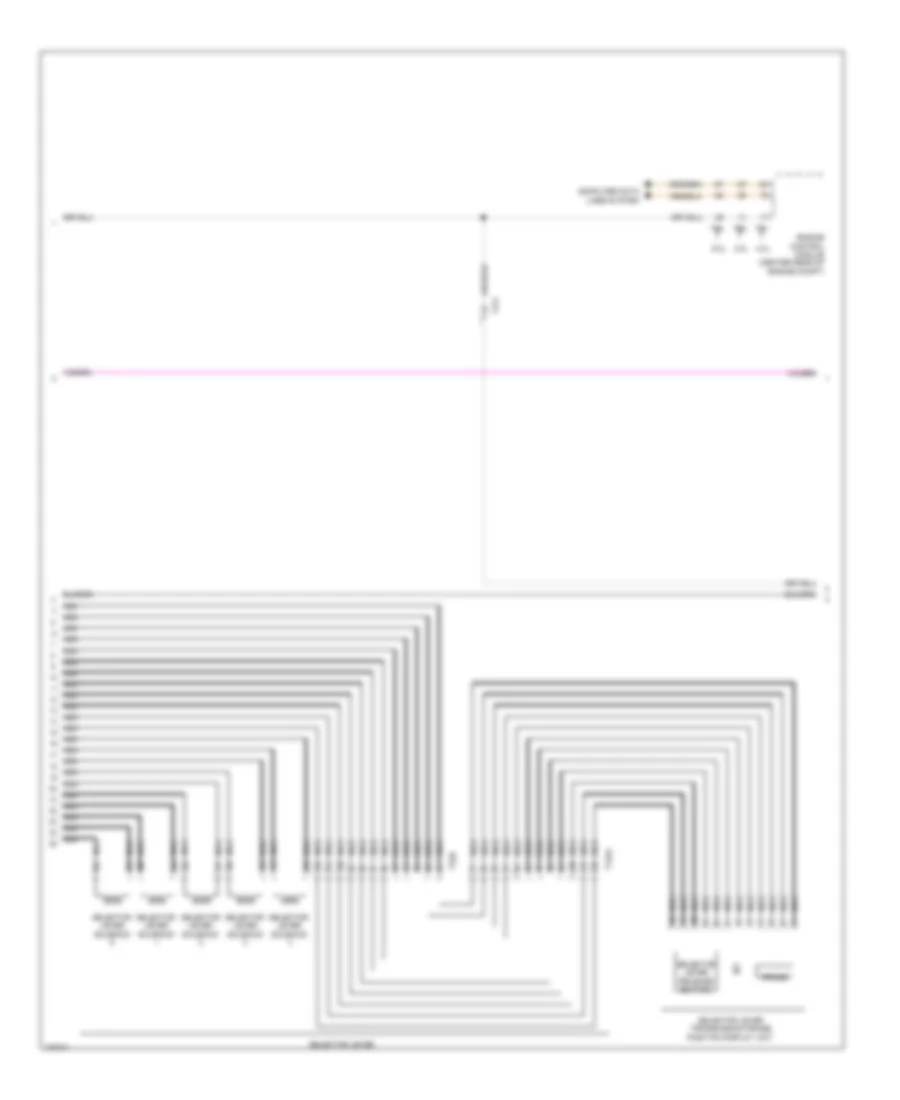
A/T Wiring Diagram (1 of 3) for Audi S8 2013

List of elements for A/T Wiring Diagram (1 of 3) for Audi S8 2013:
- 10a
- 12a
- Access/start authorization button
- Accumulator solenoid
- Automatic transmission pressure regulating valve 1
- Automatic transmission pressure regulating valve 2
- Automatic transmission pressure regulating valve 3
- Automatic transmission pressure regulating valve 4
- Automatic transmission pressure regulating valve 5
- Automatic transmission pressure regulating valve 6
- Automatic transmission pressure regulating valve 7
- Computer data lines system
- Fuse 10a
- Fuse 15a
- Fuse 5a
- Fuse carrier
- Fuse carrier 2
- Fuse carrier 3
- Fuse panel b (right end of dash)
- Fuse panel f (right front luggage compt)
- G43 (behind right kick panel)
- G687 (under front center console)
- Hot at all times
- Nca
- Parking lock sensor
- Parking lock solenoid
- Selector lever position sensor
- Selector lever sensor system control module
- Solenoid valve 1
- T10f
- T17f
- T17g
- T17o
- T22a
- T32b
- Transmission control module (tcm) (in bottom of transmission)
- Transmission fluid temperature sensor
- Transmission input speed sensor
- Transmission output speed sensor
- Vehicle electrical system control module (behind left side of dash)
A/T Wiring Diagram (2 of 3) for Audi S8 2013
List of elements for A/T Wiring Diagram (2 of 3) for Audi S8 2013:
- 3.0l
- 4.0l
- 6.3l
- Computer data lines system
- Engine control module (center rear of engine compt)
- Nca
- Prnds
- Selector lever
- Selector lever release button
- Selector lever solenoid
- Selector lever transmission range position display unit
- T12al
- T17f
- T22b
- T91
- T94
A/T Wiring Diagram (3 of 3) for Audi S8 2013
List of elements for A/T Wiring Diagram (3 of 3) for Audi S8 2013:
- 11a
- Air bag spiral spring/return spring w/ slip ring
- Comfort system central control module (right side of luggage compt)
- Computer data lines system
- Fuse 5a
- Fuse carrier 1
- Fuse panel a (right side of engine compt)
- Fuse panel f (right front luggage compt)
- G639 (on left kick panel)
- Left multi-function buttons
- Mode
- Multi-function steering wheel control module
- Nca
- Right multi-function buttons
- Steering column electronic system control module (top of steering column)
- Steering wheel control module
- T12v
- T14b
- T16d
- T32c
- T32d
- Tiptronic downshift button
- Tiptronic upshift button
- Transmission fluid cooling valve (in lower left engine compt)
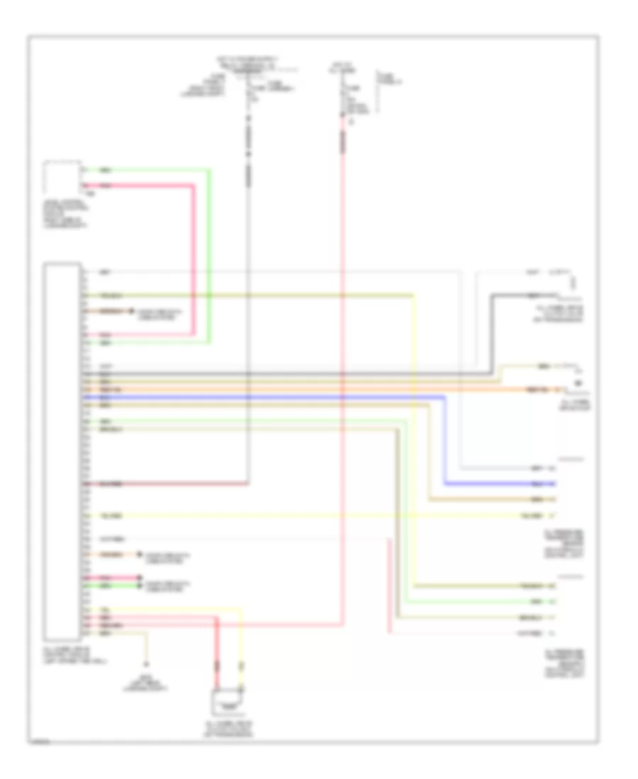
AWD Wiring Diagram for Audi S8 2013
List of elements for AWD Wiring Diagram for Audi S8 2013:
- All wheel drive clutch valve (on transmission)
- All wheel drive clutch valve 2 (on transmission)
- All wheel drive control module (left spare tire well)
- All wheel drive pump
- Computer data lines system
- Fuse 40a (or 80a) (or 150a)
- Fuse 5a
- Fuse carrier 1
- Fuse panel d
- Fuse panel f (right front luggage compt)
- G676 (left rear luggage compt)
- Hot at all times
- Level control system control module (right side of luggage compt)
- Oil pressure/ temperature sensor (on hydraulic control unit)
- Oil pressure/ temperature sensor 2 (on hydraulic control unit)
- Pnk
- Red
- T6b