TRANSMISSION
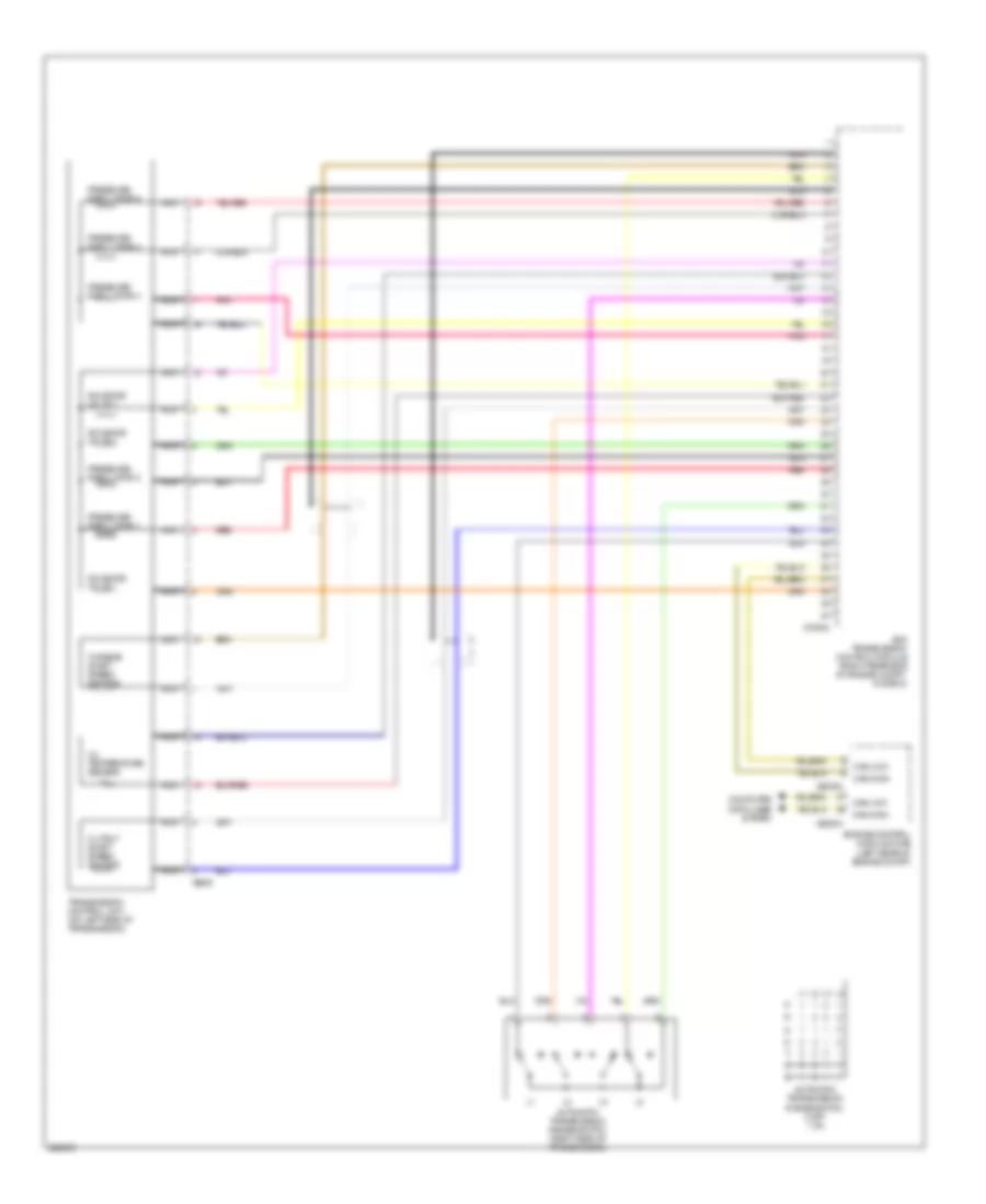
Transmission Wiring Diagram (1 of 2) for BMW 540i 2002

List of elements for Transmission Wiring Diagram (1 of 2) for BMW 540i 2002:
- (center of console) odbii connector
- Ags transmission control module (right rear side of engine compt, in e box)
- Computer data lines system
- Down shift
- E-box (right rear of engine compt)
- Electronic driveaway protection control unit (ews)
- Fuse 7.5a
- Fuse box
- Fuse f1 30a
- Fuse f38 5a
- Fuse f4 30a
- General module
- Hot at all times
- Hot in accy, run & start
- Hot in run & start
- Hot with engine relay energized
- Kick down switch
- Light module (right kick panel)
- Manual gearshift
- Off
- Park/neutral position switch (center console)
- Red
- Selector lever position switch (center console)
- Steptronic switch
- Transmission range indicator light
- Up shift
- X10012 (right side of right footwell)
- X10015
- X1193
- X1599
- X1600
- X254
- X38
- X6453 (right rear side of engine compt)
- X70001
- X70003
- X8582
Transmission Wiring Diagram (2 of 2) for BMW 540i 2002
List of elements for Transmission Wiring Diagram (2 of 2) for BMW 540i 2002:
- Ags transmission control module (right rear side of engine compt, in e box)
- Automatic transmission range switch (right side of transmission)
- Automatic transmission range switch 0 off 1 on
- Can-high
- Can-low
- Computer data lines system
- Engine control module (dme) (left rear of engine compt)
- Nca
- Oil temperature sensor
- Output shaft speed sensor
- Pnk
- Pressure regulator 1
- Pressure regulator 2
- Pressure regulator 3
- Pressure regulator 4
- Pressure regulator 5
- Red
- Solenoid valve 1
- Solenoid valve 2
- Solenoid valve 3
- Transmission control unit (on left side of transmission)
- Turbine shaft speed sensor
- X60002
- X60004
- X70004
- X8505