TRANSMISSION
A/T Wiring Diagram for BMW 640i Gran Coupe 2013

List of elements for A/T Wiring Diagram for BMW 640i Gran Coupe 2013:
- (or red)
- Computer data lines system
- Electronic transmission control (4.4l twin turbo) automatic transmission (3.0l turbo)
- Electronics junction box (jbe) (under right side of dash)
- Fuse 10a
- Fuse 7.5a
- Gear selector switch
- Gnd
- Hot w/ terminal 30b relay energized
- Left shift paddle
- Nca
- Pt-can
- Pwr sply
- Red
- Right shift paddle
- Steering column switch cluster
- Wakeup sig
- X13 11b
- Z10 6b (right kick panel)
- Z6000 5b (4.4l twin turbo) z6000 1b (3.0l turbo)
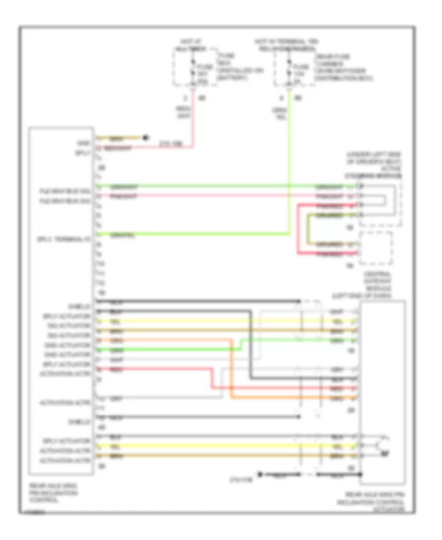
Rear Axle Wiring Diagram for BMW 640i Gran Coupe 2013
List of elements for Rear Axle Wiring Diagram for BMW 640i Gran Coupe 2013:
- (under left side of driver's seat) active steering module
- Activation actr
- Central gateway module (left end of dash)
- Flexray bus sig
- Fuse 5a
- Fuse 60a
- Fuse box (installed on battery)
- Gnd
- Gnd actuator
- Hot at all times
- Hot w/ terminal 15n relay energized
- Nca
- Pnk/red
- Rear axle king pin inclination control
- Rear axle king pin inclination control actuator
- Rear fuse carrier (in rear power distribution box)
- Red
- Shield
- Sig actuator
- Sply
- Sply actuator
- Sply, terminal15
- Z10 16b
- Z10 51b