TRANSMISSION
Rear Differential Lock Wiring Diagram for Buick Rendezvous Ultra 2005

List of elements for Rear Differential Lock Wiring Diagram for Buick Rendezvous Ultra 2005:
- (at left side of engine compt, in air cleaner assembly) (3.4l) powertrain control module (pcm)
- 3.4l
- 3.6l
- A10
- Awd ctrl
- Awd fuse 30 15a
- Body control module (in console, above fuse block, in center console)
- Breakout)
- Buick
- C3 e9
- Class 2
- Data link connector (partial) (below steering column)
- Differential clutch pump actuator check valve
- Electronic brake control module (ebcm) (left side of engine compt)
- Engine control module (ecm)
- G200 (right side of dash, on underside of cross-car beam)
- G301 (on left "b" pillar, under seat belt anchor)
- Hot in run or start
- I/p switch assembly
- Navigation system
- Pnk
- Pontiac
- S213 (4 cm from blower motor resistor)
- S333 (66 cm from center console fuse block
- Sp205 (left side of dash behind access panel)
- Tcs modc
- Trac on/off switch
- Transmission control module (tcm) (3.6l) (inside air cleaner assembly)
- Underhood fuse block (front of right wheelhouse, above battery)
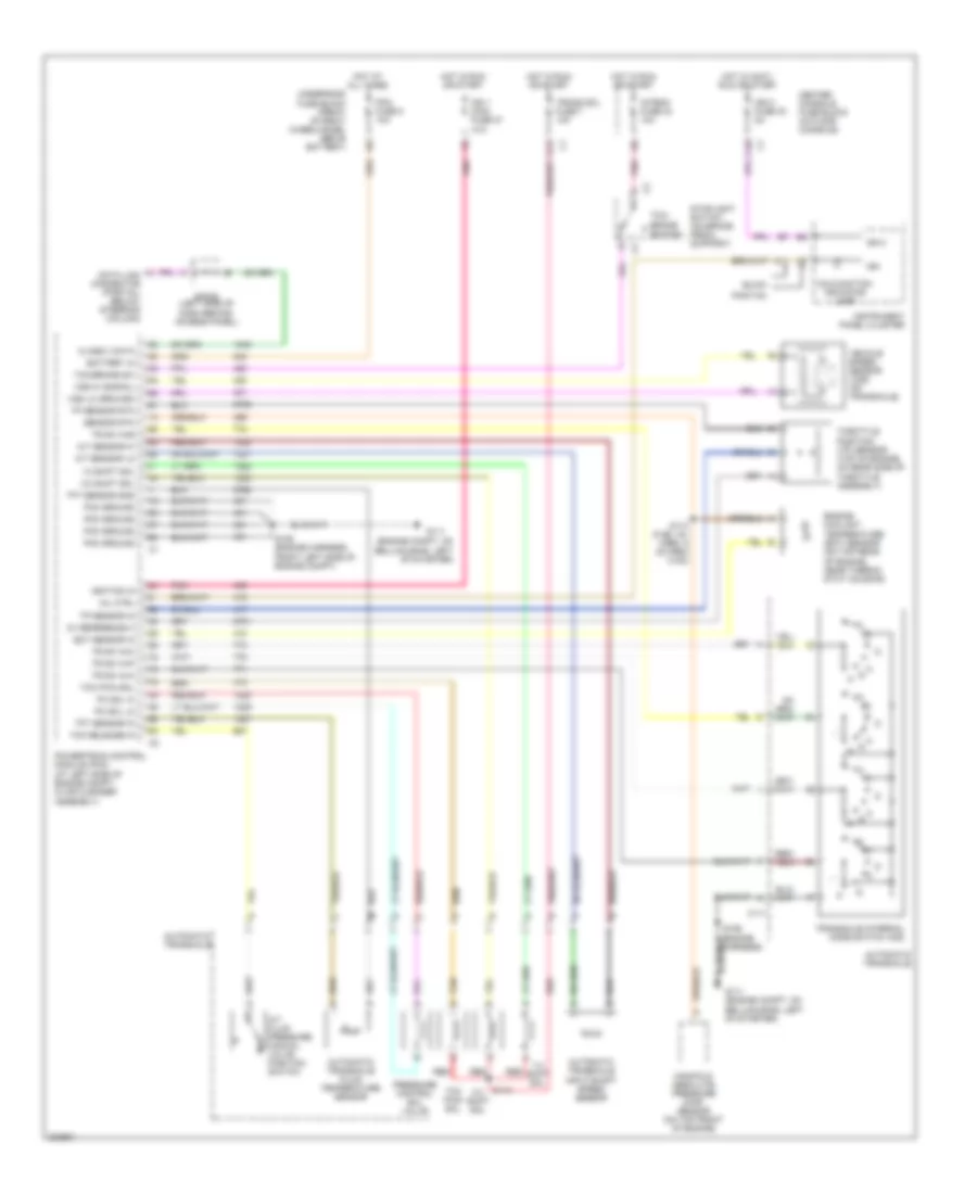
3.4L VIN E
3.4L VIN E, A/T Wiring Diagram for Buick Rendezvous Ultra 2005
List of elements for 3.4L VIN E, A/T Wiring Diagram for Buick Rendezvous Ultra 2005:
- (engine compt, on bellhousing, left of starter)
- (engine harness)
- 1-2 shift sol
- 2-3 shift sol
- 5v reference a
- A/t fluid pressure manual valve position switch
- A/t sensor hi
- A/t sensor lo
- A11
- Automatic transaxle
- Automatic transaxle fluid temperature sensor
- Automatic transaxle input shaft speed sensor
- Battery in
- Buick
- C10
- C111
- Center console fuse block (in floor console)
- Class ii data
- D12
- Data link connector (partial) (below steering column)
- Ect sensor in
- Engine coolant temperature (ect) sensor (on top rear of engine, near thermo- stat housing)
- G111
- G111 (engine compt, on bellhousing, left of starter)
- Hot at all times
- Hot in accy, run or start
- Hot in run or start
- Ign
- Ign 0
- Ign 0 fuse 30 2a
- Ign 1 main fuse 27 10a
- Ignition in
- Instrument panel cluster
- Intemm fuse 24 10a
- Malfunction indicator lamp
- Manifold absolute pressure (map) sensor (on top front of engine)
- Mil ctrl
- Pc sol hi
- Pc sol lo
- Pcm fuse 5 10a
- Pcm ground
- Pnk
- Pontiac
- Powertrain control module (pcm) (at left side of engine compt, in air cleaner assembly)
- Pressure control sol valve
- Red
- S106
- S106 (engine harness, front left side of engine compt)
- S110 (fuel inj harn, 5 cm from c102)
- S115
- Sensor rtn
- Sp205 (left side of dash behind access panel)
- Stoplight switch (on brake pedal support)
- Tan b
- Tcc pwm sol
- Tcc release in
- Tcc/ brake switch
- Tcc/brake sw
- Tft sensor gnd
- Tft sensor in
- Throttle position (tp) sensor (top of engine, on rear side of throttle assembly)
- Tp sensor in
- Tp sensor rtn
- Tr sw in-a
- Tr sw in-b
- Tr sw in-c
- Tr sw in-p
- Trans sol fuse 7 10a
- Transaxle internal mode switch (ims)
- Underhood fuse block (front of right wheelhouse, above battery)
- Vehicle speed sensor (vss) (on transaxle)
- Vss hi (signal)
- Vss lo (ground)
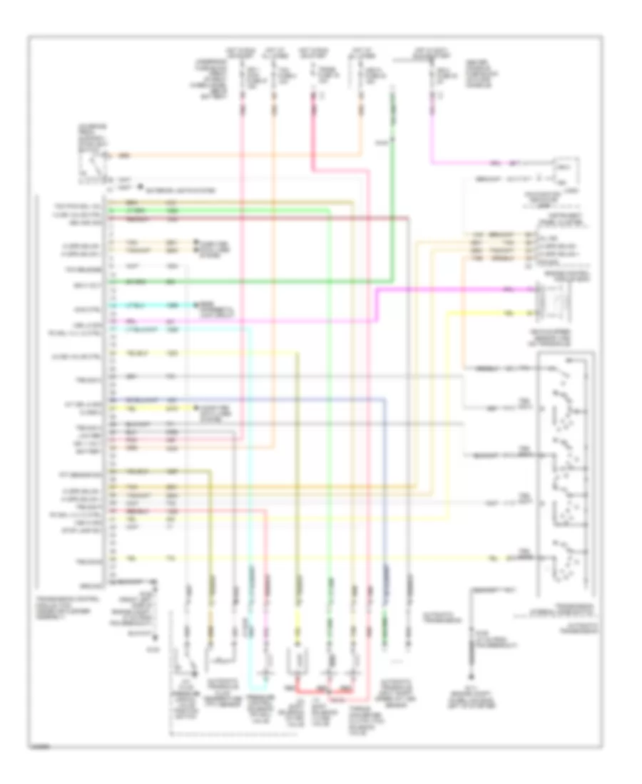
3.6L VIN 7
3.6L VIN 7, A/T Wiring Diagram for Buick Rendezvous Ultra 2005
List of elements for 3.6L VIN 7, A/T Wiring Diagram for Buick Rendezvous Ultra 2005:
- (on brake pedal support) stoplight switch
- 1-2 shift solenoid (1-2 ss) valve
- 1-2 ss valve ctrl
- 2-3 shift solenoid (2-3 ss) valve
- 2-3 ss valve ctrl
- A/t fluid pressure manual valve position switch
- A/t iss lo sig
- A11
- Automatic transaxle fluid temperature (tft) sensor
- Automatic transaxle input shaft speed (a/t iss) sensor
- Automatic transmission
- Awd ctrl
- Battery
- C10
- Center console fuse block (in floor console)
- Class 2
- Computer data lines system
- D11
- Engine control module (ecm)
- Exterior lights system
- G111 (engine compt, on bellhousing, left of starter)
- G132
- Ground
- Hi spd gmlan +
- Hi spd gmlan -
- Hot at all times
- Hot in accy, run or start
- Hot in run or start
- Hzd fl fuse 40 15a
- Ign
- Ign 0
- Ign 0 fuse 30 2a
- Ign 0 volt
- Ign 1 main fuse 27 15a
- Ign 1 volt
- Instrument panel cluster
- Iss high sig
- Logic
- Low ref
- Malfunction indicator lamp
- Mil ind
- P/n
- P/n sig
- Pc sol vlv hi ctrl
- Pc sol vlv lo ctrl
- Pnk
- Pressure control solenoid (pc sol) valve
- Rear differental lock circuit
- Red
- S106 (47 cm from pcm breakout)
- S106 (front left side of engine compt, 47 cm from pcm breakout)
- S115
- S140
- Stop lamp sw
- Tan
- Tan b
- Tcc pwm sol vol
- Tcc release
- Tcm fuse 8 10a
- Tft sensor sig
- Torque converter clutch (tcc) solenoid valve
- Trans fuse 16 10a
- Transmission control module (tcm) (inside air cleaner assembly)
- Transmission internal mode switch
- Trs sig a
- Trs sig b
- Trs sig c
- Trs sig p
- Underhood fuse block (front of right wheelhouse, above battery)
- Vehicle speed sensor (vss) (on transaxle)
- Vss hi sig
- Vss lo sig