TRANSMISSION
A/T Wiring Diagram (1 of 2) for Cadillac XLR V 2007

List of elements for A/T Wiring Diagram (1 of 2) for Cadillac XLR V 2007:
- Acc/tcm fuse 3 10a
- Accessory voltage
- Automatic transmission
- Battery pos volt
- Battery positive volt
- Computer data lines system
- D11
- Data bus +
- Data bus -
- E11
- Ecm/tcm fuse 11 15a
- G106
- Gear high trans temp service trans shift to prk
- Gmlan (ecm)
- Ground
- Heads up display (hud) (top left side of dash)
- Hot at all times
- Hot in run or start
- Hud class 2 serial data
- Hud message center
- Ignition 1 voltage
- In speed sensor sig
- Input/output speed sensors (iss/oss) assembly
- Instrument panel cluster (ipc)
- Internal mode switch (ims) assembly
- Ipc class 2 serial data
- Iss signal
- Logic
- Message center
- Message request (tcm)
- Nca
- Oss signal
- Out speed sensor sig
- Park/neutral sig
- Pnk
- Power distribution system
- Range signal a
- Range signal b
- Range signal c
- Range signal p
- Red
- Sp106 (right rear of engine compt by battery)
- Stop lamp sw sig
- Tan
- Tap up/dn sw sig
- Tap up/dwn gear
- Tehc module assembly
- Underhood fuse block (right rear of engine compt)
- Up-shift ind
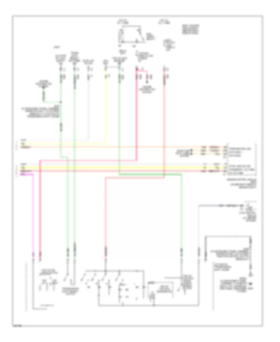
A/T Wiring Diagram (2 of 2) for Cadillac XLR V 2007
List of elements for A/T Wiring Diagram (2 of 2) for Cadillac XLR V 2007:
- Acc volt
- Accessory voltage
- Automatic transmission shift lever
- B+ voltage
- Body control module (bcm) (behind right side of dash)
- Btsi sol/col lock fuse 10 10a
- Computer data lines system
- Data bus +
- Data bus -
- Engine control module (ecm) (lower right rear of engine compt)
- G202
- Hot at all times
- Hvac control module (at center of dash)
- I/p lamp ctrl
- Logic
- Park/neutral sig
- Pnk
- Power distribution system
- Relay cntl
- Run/ crank relay 7
- S246 (in instrument panel harness, approximately 8.5 cm from traction control switch breakout)
- S276 (in instrument panel harness, approximately 14.5 cm from breakout to automatic transmission shift lever)
- Sp202 (in instrument panel harness, at base of right a pillar behind trim panel, grounded to g202)
- Stop lamp sw sig
- Stop lmp sw sig
- Tan
- Tap dwn -
- Tap up +
- Tap up/ dwn enabled sig
- Tap up/ tap dwn enabled sig
- Tap up/ tap dwn trans- mission enable switch
- Tap up/tap down switch
- Trans shift select sw (park) sig
- Transmission shift select switch
- Tutd sw/ strg col sw fuse 28 2a