TRANSMISSION
4.3L
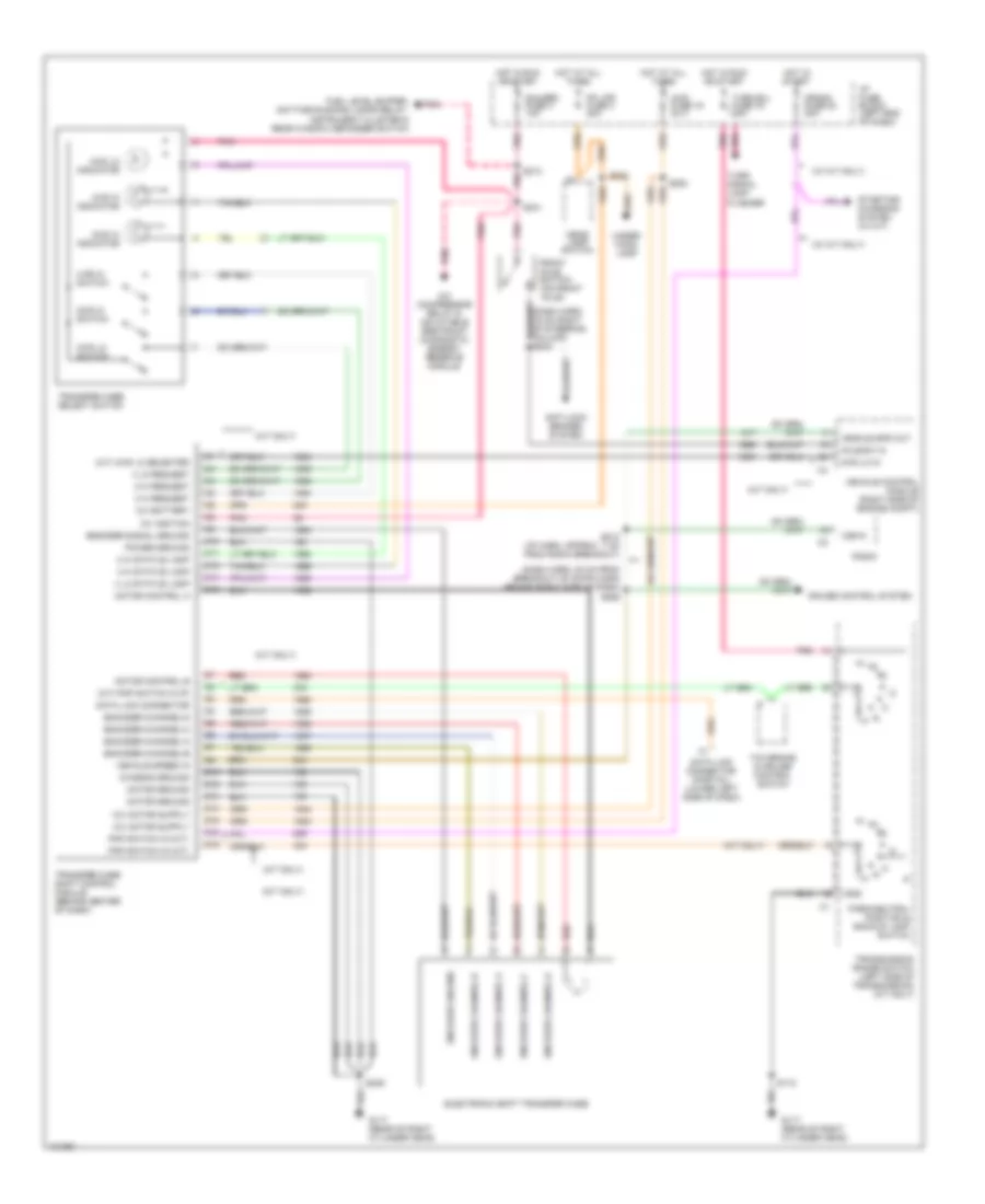
4.3L (VIN W), Transmission Wiring Diagram, 4L60-E for Chevrolet Blazer 1997

List of elements for 4.3L (VIN W), Transmission Wiring Diagram, 4L60-E for Chevrolet Blazer 1997:
- (behind left side of dash)
- (eng harn, 19 cm from inj harn breakout) s115
- (twisted wire pair)
- 1-2 shift sol
- 1-2 shift sol ctrl
- 2-3 shift sol
- 2-3 shift sol ctrl
- 3-2 shift sol
- 3-2 sol ctrl
- 5v reference
- All times
- And start
- Anti-lock brakes system
- Automatic transmission (4l60-e)
- Battery feed
- Brake fuse 12 10a
- Brake pressure modulator valve, cruise control module & cruise control switch
- Brake signal
- Cruise control system
- Data link connector (partial) (below left side of dash)
- Ecm batt
- Ecm ign fuse 10 20a
- Ect signal
- Electronic ignition control module, crankshaft position sensor, ignition coil & fuel injectors)
- Engine controls system
- Engine coolant temperature sensor (thermostat housing)
- Fuel pump relay
- Fuel pump switch/ engine oil pressure gauge sensor
- Fuse 9 20a
- G114 (rear of left cylinder head)
- G117 (rear of right cylinder head)
- Gauges fuse 4 10a
- Hot at
- Hot in
- Hot in run
- Hot in run, bulb
- I/p fuse block
- Ignition feed
- Instrument cluster
- Malfunction indicator lamp
- Mil ctrl
- Park pawl actuator (w/ a/t) & instrument cluster
- Park pawl actuator (w/ floor shift) or instrument cluster (w/ column shift)
- Pickup
- Pnk
- Press ctrl so hi
- Press ctrl sol lo
- Pressure control solenoid
- Range signal-a
- Range signal-b
- Range signal-c
- Red
- Rev
- Run
- Run feed
- S100 (eng harn 30 cm from vcm breakout)
- S106
- S108
- S140
- S220
- S227 (dash harn, approx 8 cm from data link conn breakout)
- S238 (dash harn, approx 11 cm from tcc brake & cruise control rel sw breakout)
- S239
- S266
- Sensor ground
- Serial data
- Shield
- System gnd
- Tan
- Tcc brake & cruise control release switch (on brake pedal bracket)
- Tcc pwm sol
- Tcc pwm sol ctrl
- Tcc sol
- Tcc sol ctrl
- Test or start
- Tft signal
- Throttle position sensor
- Tp signal
- Trans fuse 24 10a
- Transmission fluid temperature sensor
- Transmission range pressure switch assembly
- Utility
- Vehicle control module (right side of engine compt)
- Vehicle speed sensor (on transmission-2wd) (on transfer case-4wd)
- Vss hi
- Vss lo
Electronic Transfer Case Wiring Diagram for Chevrolet Blazer 1997
List of elements for Electronic Transfer Case Wiring Diagram for Chevrolet Blazer 1997:
- (a/t only)
- (a/t) 4wd lo selected
- (a/t) pnp switch in (p)
- (dash harn, 20 cm from breakout of 23-pin conn behind right side of dash) s259
- (m/t only)
- (w/ m/t only)
- 12v battery
- 12v ignition
- 2 hi request
- 2 hi status lamp
- 2wd hi indicator
- 2wd hi switch
- 4 hi request
- 4 hi status lamp
- 4 lo request
- 4 lo status lamp
- 4wd fuse 19 20 a
- 4wd hi indicator
- 4wd hi switch
- 4wd lo in
- 4wd lo indicator
- 4wd lo switch
- A/c compressor relay & inflatable restraint diagnostic energy reserve module
- Anti-lock brakes system
- Axle sw in
- C10
- C11
- C12
- C14
- C16
- Chassis ground
- Crank fuse 20 20a
- Cruise control system
- D10
- D12
- D13
- D14
- D15
- D16
- Data link connector
- Data link connector (partial) (lower left side of dash)
- Electronic shift transfer case
- Encoder channel a
- Encoder channel b
- Encoder channel c
- Encoder channel d
- Encoder channel-a
- Encoder channel-b
- Encoder channel-c
- Encoder channel-d
- Encoder ground
- Encoder signal ground
- Front axle switch (on front axle)
- Fuel level buffer, daytime running lamps relay, instrument cluster & rear window defogger switch
- G117 (rear of right cylinder head)
- Gauges fuse 4 10a
- Gnd
- Head- lamp switch
- Hot at all times
- Hot in run or start
- Hot in start
- I/p fuse block (left end of dash)
- Motor control a
- Motor control b
- Motor ground
- Park/neutral position & backup lamp switch
- Pk lps fuse 3 20a
- Pnk
- Pnp switch in (a/t)
- Pnp switch in (m/t)
- Power ground
- Radio
- Red
- S112
- S212 (i/p harn, approx 7 cm from radio breakout)
- S213
- S241
- S242
- S246
- S253
- Starting/ charging system (w/ m/t)
- Tcc brake & cruise control switch
- Transfer case select switch
- Transfer case shift control module (behind center of dash)
- Transmission range switch (left side of transmission) (a/t only)
- Turn b/u fuse 16 15a
- Turn signal lamp flasher
- Under- hood lamp
- Vehicle control module (right side of engine compt)
- Vehicle spd out
- Vehicle speed in
- Vss in