TRANSMISSION
5.7L
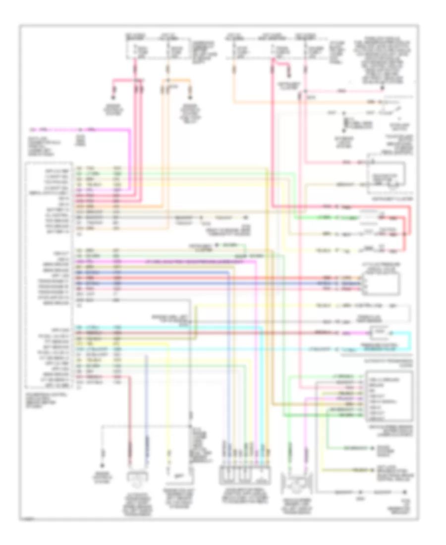
5.7L VIN R, A/T Wiring Diagram, 4L60-E for Chevrolet Cutaway G3500 2000

List of elements for 5.7L VIN R, A/T Wiring Diagram, 4L60-E for Chevrolet Cutaway G3500 2000:
- (dash harn, near
- (eng harn, 98 cm
- 1-2 shift sol
- 1-2 ss
- 2-3 shift sol
- 2-3 ss
- 3-2 downshift sol
- 3-2 ss
- 5v reference
- A/t fluid pressure manual valve position switch
- Anti-lock brakes system
- Anti-lock brakes system (electronic brake control module)
- Automatic transmission (4l60-e)
- B17
- Battery in
- Brake fuse 18 10a
- Brake switch input
- Cruise control system
- Data class ii
- Data link connector (dlc) (partial) (under left side of dash)
- Ecm-b fuse 20a
- Ecm-i fuse 20a
- Ect sens input
- Engine controls system
- Engine controls system (fuel injectors)
- Engine controls system (fuel pump relay)
- Engine coolant temperature (ect) sensor (on top front of engine)
- From underhood fuse block, toward a/c compressor clutch breakout)
- G125 (front of engine, near thermostat housing)
- Gauges fuse 4 10a
- Hot at all times
- Hot in off, run, or start
- Hot in run
- Hot in run or start
- I/p fuse block (on left lower kick panel)
- Ignition in
- Instrument cluster
- Malfunction indicator lamp
- Mil control
- Park brake warning switch breakout)
- Passlock module, fuel sender buffer module, headlamp leveling switch, multifunction alarm module, vehicle speed sensor buffer, low engine coolant level indicator module, convenience center, drl control module, headlamp switch, ip relay center, left/right headlamp leveling actuators
- Pcm ground
- Pcs sol hi out
- Pcs sol lo out
- Pnk
- Pressure control solenoid valve
- Range signal "a"
- Range signal "b"
- Range signal "c"
- Red
- S102
- S120
- S122
- S132
- S133 (5.0l & 5.7l only) pnk
- S136 (engine harn)
- S139 (eng harn)
- S153 (eng harn)
- S154
- S210
- S216
- S231
- Sensor ground
- Sensor return
- Tan
- Tcc pwm sol
- Tcc sol
- Tcc/abs/ cruise switch
- Tcc/stoplamp switch (behind dash, on brake pedal support)
- Throttle position (tp) sensor (on side of throttle body)
- Tp sens input
- Trans fluid temp sensor
- Trans fuse 20 10a
- Trans temp sig in
- Underhood fuse/relay center (on left side of engine compt)
- Vehicle control module (vcm) (on left side of engine compt)
- Vehicle speed sensor (vss) (on left side of transmission)
- Vss hi (signal)
- Vss lo (ground)
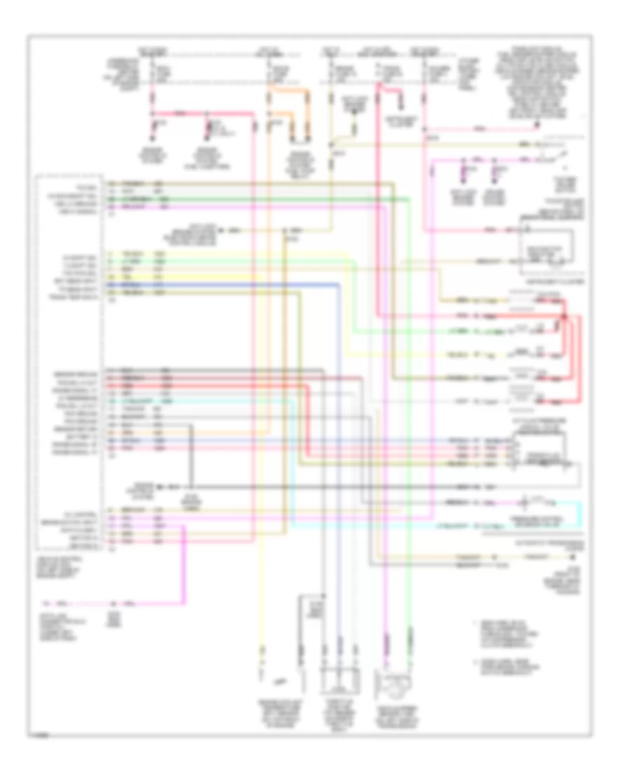
5.7L VIN R, A/T Wiring Diagram, 4L80-E for Chevrolet Cutaway G3500 2000
List of elements for 5.7L VIN R, A/T Wiring Diagram, 4L80-E for Chevrolet Cutaway G3500 2000:
- (dash harn, near
- (eng harn, 98 cm
- 2-3 shift sol
- 2-3 ss
- 3-2 shift sol
- 3-2 ss
- 5v reference
- A/t fluid pressure manual valve position switch
- A/t iss hi
- A/t iss lo
- Anti-lock brakes system
- Anti-lock brakes system (electronic brake control module)
- Automatic transmission (4l80-e)
- Automatic transmission input shaft speed sensor (on left side of transmission)
- B17
- Battery in
- Brake fuse 18 10a
- Brake switch input
- Cruise control system
- Data class ii
- Data link connector (dlc) (partial) (under left side of dash)
- Ecm-b fuse 20a
- Ecm-i fuse 20a
- Ect sens input
- Engine controls system
- Engine controls system (fuel injectors)
- Engine controls system (fuel pump relay)
- Engine coolant temperature (ect) sensor (on top front of engine)
- From underhood fuse block, toward a/c compressor clutch breakout)
- G125 (front of engine, near thermostat housing)
- Gauges fuse 4 10a
- Hot at all times
- Hot in off, run, or start
- Hot in run
- Hot in run or start
- I/p fuse block (on left lower kick panel)
- Ignition in
- Instrument cluster
- Malfunction indicator lamp
- Mil control
- Park brake warning switch breakout)
- Passlock module, fuel sender buffer module, headlamp leveling switch, multifunction alarm module, vehicle speed sensor buffer, low engine coolant level indicator module, convenience center, drl control module, headlamp switch, ip relay center, left/right headlamp leveling actuators
- Pcm ground
- Pcs sol hi out
- Pcs sol lo out
- Pnk
- Pressure control solenoid valve
- Range signal "a"
- Range signal "b"
- Range signal "c"
- Red
- S102
- S120
- S122
- S132
- S133 (5.0l & 5.7l only) pnk
- S136 (engine harn)
- S139 (eng harn)
- S153 (eng harn)
- S154
- S210
- S216
- S231
- Sensor ground
- Sensor return
- Tcc pwm sol
- Tcc/abs/ cruise switch
- Tcc/stoplamp switch (behind dash, on brake pedal support)
- Throttle position (tp) sensor (on side of throttle body)
- Tp sens input
- Trans fluid temp sensor
- Trans fuse 20 10a
- Trans temp sig in
- Underhood fuse/relay center (on left side of engine compt)
- Vehicle control module (vcm) (on left side of engine compt)
- Vehicle speed sensor (vss) (on left side of transmission)
- Vss hi (signal)
- Vss lo (ground)
6.5L
6.5L VIN F, A/T Wiring Diagram for Chevrolet Cutaway G3500 2000
List of elements for 6.5L VIN F, A/T Wiring Diagram for Chevrolet Cutaway G3500 2000:
- (engine harn, left top of engine) s124
- (ip harn, 23 cm from vss buffer module breakout)
- 1-2 shift sol
- 1-2 ss
- 2-3 shift sol
- 2-3 ss
- A/t fluid pressure manual valve position switch
- A/t iss sens hi
- A/t iss sens lo
- A12
- Accelerator pedal position (app) module (below dash, attached to accelerator pedal)
- Anti-lock brakes system (electronic brake control module)
- App 1 5v ref
- App 1 sig
- App 2 5v ref
- App 2 sig
- App 3 5v ref
- App 3 sig
- Automatic transmission (4l80-e)
- Automatic transmission input shaft speed sensor (on left side of transmission)
- B10
- B12
- B17
- Battery in
- C11
- C12
- C13
- C14
- C15
- D11
- D12
- D13
- Data link connector (dlc) (partial) (under left side of dash)
- Ecm-b fuse 20a
- Ecm-i fuse 20a
- Ect sens sig
- Engine controls system
- Engine controls system (fuel pump relay)
- Engine coolant temperature (ect) sensor (on top front of engine)
- Exterior lights system
- G125 (at generator bracket)
- G125 (front of engine, near thermostat housing)
- Gauges fuse 4 10a
- Ground
- Hot at all times
- Hot in off, run, or start
- Hot in run or start
- I/p fuse block (on left lower kick panel)
- Ign
- Ign in
- Instrument cluster
- Malfunction indicator lamp
- Mil control
- Passlock module, fuel sender buffer module, headlamp leveling switch, multifunction alarm module, low engine coolant level indicator module, convenience center, drl control module, headlamp switch, ip relay center, left/right headlamp leveling actuators
- Pc sol valve hi
- Pc sol valve lo
- Pcm ground
- Pnk
- Powertrain control module (pcm) (behind center of dash)
- Pressure control solenoid valve
- Red
- S102
- S115 (engine jumper harn, near optical fuel temp sensor breakout)
- S117
- S120
- S153 (eng harn)
- S216
- S238
- S254
- Sens ground
- Serial data class ii
- Sound systems (radio)
- Stop fuse 1 20a
- Stoplamp sw in
- Stoplamp switch
- Tan
- Tcc pwm sol
- Tcc/stoplamp switch (behind dash, on brake pedal support)
- Tft sens sig
- Trans fluid temp sensor
- Trans fuse 20 10a
- Trans range "a"
- Trans range "b"
- Trans range "c"
- Underhood fuse/relay center (on left side of engine compt)
- Vehicle speed sensor (vss) (on left side of transmission)
- Vehicle speed sensor buffer module (under glove box)
- Vss hi (signal)
- Vss in
- Vss lo (ground)
- Vss out
7.4L
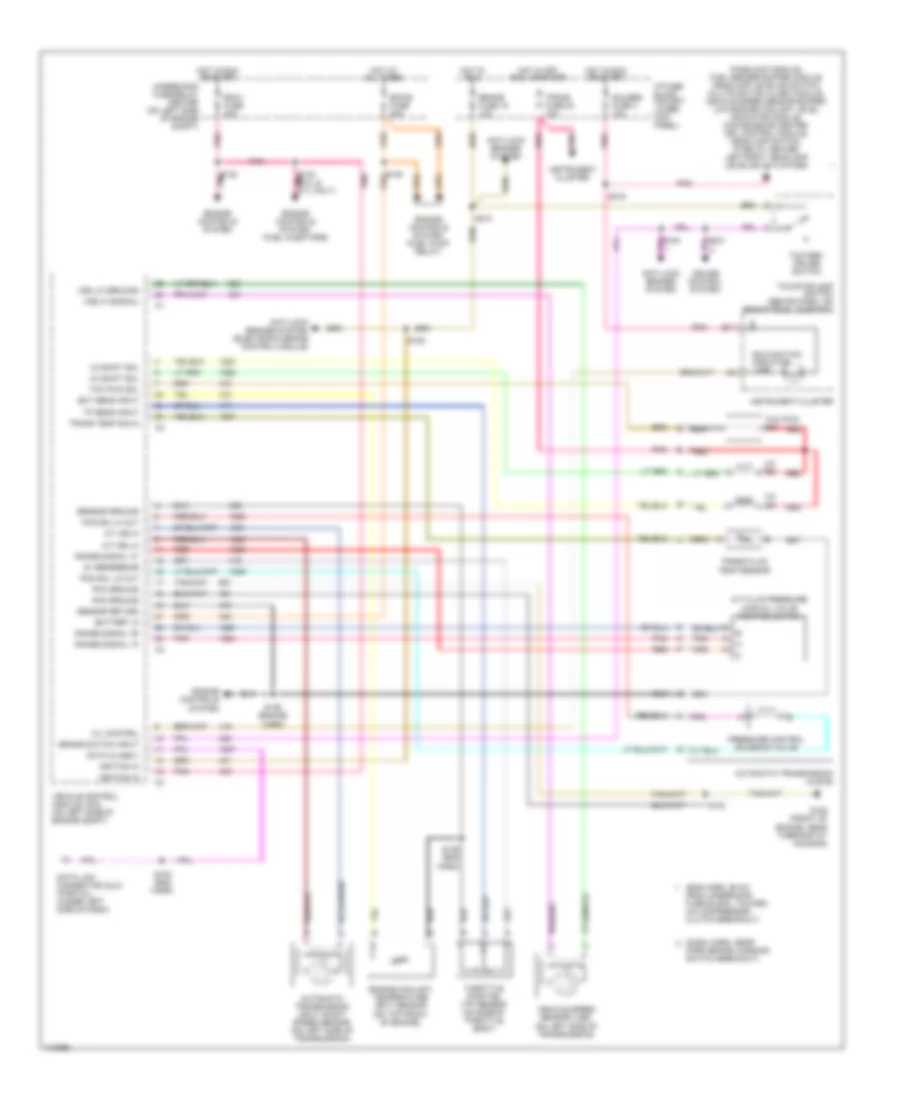
7.4L VIN J, A/T Wiring Diagram, 4L60-E for Chevrolet Cutaway G3500 2000
List of elements for 7.4L VIN J, A/T Wiring Diagram, 4L60-E for Chevrolet Cutaway G3500 2000:
- (dash harn, near
- (eng harn, 98 cm
- 1-2 shift sol
- 1-2 ss
- 2-3 shift sol
- 2-3 ss
- 3-2 downshift sol
- 3-2 ss
- 5v reference
- A/t fluid pressure manual valve position switch
- Anti-lock brakes system
- Anti-lock brakes system (electronic brake control module)
- Automatic transmission (4l60-e)
- B17
- Battery in
- Brake fuse 18 10a
- Brake switch input
- Cruise control system
- Data class ii
- Data link connector (dlc) (partial) (under left side of dash)
- Ecm-b fuse 20a
- Ecm-i fuse 20a
- Ect sens input
- Engine controls system
- Engine controls system (fuel injectors)
- Engine controls system (fuel pump relay)
- Engine coolant temperature (ect) sensor (on top front of engine)
- From underhood fuse block, toward a/c compressor clutch breakout)
- G125 (front of engine, near thermostat housing)
- Gauges fuse 4 10a
- Hot at all times
- Hot in off, run, or start
- Hot in run
- Hot in run or start
- I/p fuse block (on left lower kick panel)
- Ignition in
- Instrument cluster
- Malfunction indicator lamp
- Mil control
- Park brake warning switch breakout)
- Passlock module, fuel sender buffer module, headlamp leveling switch, multifunction alarm module, vehicle speed sensor buffer, low engine coolant level indicator module, convenience center, drl control module, headlamp switch, ip relay center, left/right headlamp leveling actuators
- Pcm ground
- Pcs sol hi out
- Pcs sol lo out
- Pnk
- Pressure control solenoid valve
- Range signal "a"
- Range signal "b"
- Range signal "c"
- Red
- S102
- S120
- S122
- S132
- S133 (5.0l & 5.7l only) pnk
- S136 (engine harn)
- S139 (eng harn)
- S153 (eng harn)
- S154
- S210
- S216
- S231
- Sensor ground
- Sensor return
- Tan
- Tcc pwm sol
- Tcc sol
- Tcc/abs/ cruise switch
- Tcc/stoplamp switch (behind dash, on brake pedal support)
- Throttle position (tp) sensor (on side of throttle body)
- Tp sens input
- Trans fluid temp sensor
- Trans fuse 20 10a
- Trans temp sig in
- Underhood fuse/relay center (on left side of engine compt)
- Vehicle control module (vcm) (on left side of engine compt)
- Vehicle speed sensor (vss) (on left side of transmission)
- Vss hi (signal)
- Vss lo (ground)
7.4L VIN J, A/T Wiring Diagram, 4L80-E for Chevrolet Cutaway G3500 2000
List of elements for 7.4L VIN J, A/T Wiring Diagram, 4L80-E for Chevrolet Cutaway G3500 2000:
- (dash harn, near
- (eng harn, 98 cm
- 2-3 shift sol
- 2-3 ss
- 3-2 shift sol
- 3-2 ss
- 5v reference
- A/t fluid pressure manual valve position switch
- A/t iss hi
- A/t iss lo
- Anti-lock brakes system
- Anti-lock brakes system (electronic brake control module)
- Automatic transmission (4l80-e)
- Automatic transmission input shaft speed sensor (on left side of transmission)
- B17
- Battery in
- Brake fuse 18 10a
- Brake switch input
- Cruise control system
- Data class ii
- Data link connector (dlc) (partial) (under left side of dash)
- Ecm-b fuse 20a
- Ecm-i fuse 20a
- Ect sens input
- Engine controls system
- Engine controls system (fuel injectors)
- Engine controls system (fuel pump relay)
- Engine coolant temperature (ect) sensor (on top front of engine)
- From underhood fuse block, toward a/c compressor clutch breakout)
- G125 (front of engine, near thermostat housing)
- Gauges fuse 4 10a
- Hot at all times
- Hot in off, run, or start
- Hot in run
- Hot in run or start
- I/p fuse block (on left lower kick panel)
- Ignition in
- Instrument cluster
- Malfunction indicator lamp
- Mil control
- Park brake warning switch breakout)
- Passlock module, fuel sender buffer module, headlamp leveling switch, multifunction alarm module, vehicle speed sensor buffer, low engine coolant level indicator module, convenience center, drl control module, headlamp switch, ip relay center, left/right headlamp leveling actuators
- Pcm ground
- Pcs sol hi out
- Pcs sol lo out
- Pnk
- Pressure control solenoid valve
- Range signal "a"
- Range signal "b"
- Range signal "c"
- Red
- S102
- S120
- S122
- S132
- S133 (5.0l & 5.7l only) pnk
- S136 (engine harn)
- S139 (eng harn)
- S153 (eng harn)
- S154
- S210
- S216
- S231
- Sensor ground
- Sensor return
- Tcc pwm sol
- Tcc/abs/ cruise switch
- Tcc/stoplamp switch (behind dash, on brake pedal support)
- Throttle position (tp) sensor (on side of throttle body)
- Tp sens input
- Trans fluid temp sensor
- Trans fuse 20 10a
- Trans temp sig in
- Underhood fuse/relay center (on left side of engine compt)
- Vehicle control module (vcm) (on left side of engine compt)
- Vehicle speed sensor (vss) (on left side of transmission)
- Vss hi (signal)
- Vss lo (ground)