TRANSMISSION
2.2L VIN F
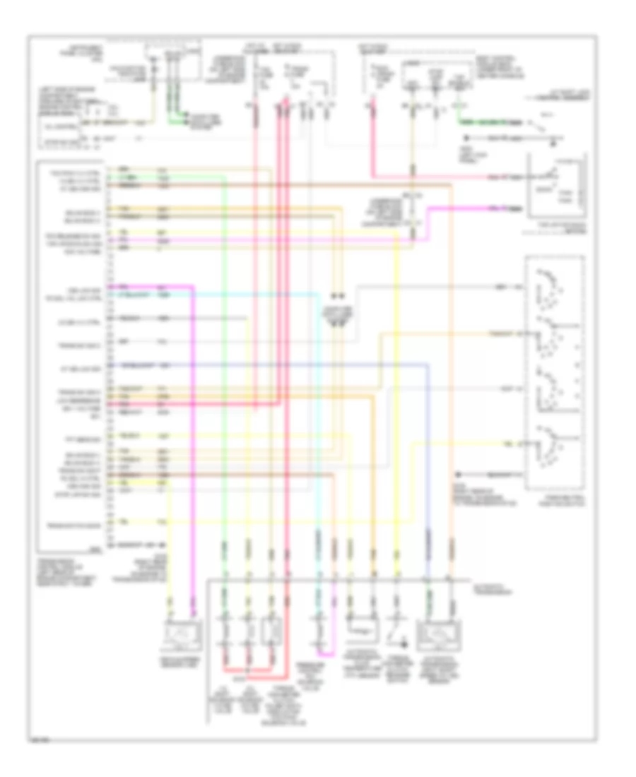
2.2L VIN F, A/T Wiring Diagram for Chevrolet Malibu LS 2007

List of elements for 2.2L VIN F, A/T Wiring Diagram for Chevrolet Malibu LS 2007:
- (left kick panel)
- (left side of engine compartment, forward of battery) engine control module (ecm)
- (tft) sensor
- 1-2 shift solenoid (1-2 ss) valve
- 1-2 ss vlv ctrl
- 10a
- 2-3 shift solenoid (2-3 ss) valve
- 2-3 ss vlv ctrl
- 3.5l 2.2l
- A/t shift lock control assembly
- Acc volt
- Acc voltage
- At iss high sig
- At iss low sig
- Automatic transmission
- Automatic transmission fluid temperature
- Automatic transmission input shaft speed (at iss) sensor
- B(+)
- Body control module (bcm) (under front of center console)
- C9 pnk
- Computer data lines system
- Down
- G105 (right rear of engine, on engine to transmission stud)
- G303
- Gmlan bus (+)
- Gmlan bus (-)
- Gmlan data
- Gnd
- Hot at all times
- Hot in run or start
- Ign 1
- Ign 1 voltage
- Instrument panel cluster (ipc)
- Logic
- Low reference
- Malfunction indicator lamp
- Mil control
- Nca
- Park/neutral position switch
- Pc sol hi ctrl
- Pc sol val low ctrl
- Pnk
- Pressure control (pc) solenoid valve
- Red
- Run/ crank fuse 2a
- S103
- Stop lamp sw sig
- Stop lmp sw sig
- Stop sw sig
- Tan
- Tap enable sig
- Tap up/down sw sig
- Tap up/tap down switch
- Tcc pwm vlv ctrl
- Tcc release sw sig
- Tcm fuse
- Tft sens sig
- Torque converter clutch pulse width modulation (tcc pwm) solenoid valve
- Torque converter clutch release switch
- Trans fuse 10a
- Trans sw sig a
- Trans sw sig c
- Trans sw sig p
- Trans switch sig b
- Transmission control module (left rear of engine compartment, near strut tower)
- Underhood fuse block (on left side of engine compartment)
- Vehicle speed sensor (vss)
- Vss high sig
- Vss low sig
3.5L VIN N
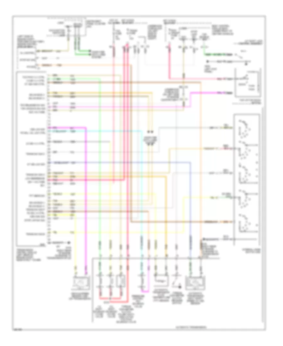
3.5L VIN N, A/T Wiring Diagram for Chevrolet Malibu LS 2007
List of elements for 3.5L VIN N, A/T Wiring Diagram for Chevrolet Malibu LS 2007:
- (left kick panel)
- (left side of engine compartment, forward of battery) engine control module (ecm)
- (tft) sensor
- 1-2 shift solenoid (1-2 ss) valve
- 1-2 ss vlv ctrl
- 10a
- 2-3 shift solenoid (2-3 ss) valve
- 2-3 ss vlv ctrl
- 3.5l 2.2l
- A/t shift lock control assembly
- Acc volt
- Acc voltage
- At iss high sig
- At iss low sig
- Automatic transmission
- Automatic transmission fluid temperature
- Automatic transmission input shaft speed (at iss) sensor
- B(+)
- Body control module (bcm) (under front of center console)
- C9 pnk
- Computer data lines system
- Down
- G105 (right rear of engine, on engine to transmission stud)
- G303
- Gmlan bus (+)
- Gmlan bus (-)
- Gmlan data
- Gnd
- Hot at all times
- Hot in run or start
- Ign 1
- Ign 1 voltage
- Instrument panel cluster (ipc)
- Logic
- Low reference
- Malfunction indicator lamp
- Mil control
- Nca
- Park/neutral position switch
- Pc sol hi ctrl
- Pc sol val low ctrl
- Pnk
- Pressure control (pc) solenoid valve
- Red
- Run/ crank fuse 2a
- S103
- Stop lamp sw sig
- Stop lmp sw sig
- Stop sw sig
- Tan
- Tap enable sig
- Tap up/down sw sig
- Tap up/tap down switch
- Tcc pwm vlv ctrl
- Tcc release sw sig
- Tcm fuse
- Tft sens sig
- Torque converter clutch pulse width modulation (tcc pwm) solenoid valve
- Torque converter clutch release switch
- Trans fuse 10a
- Trans sw sig a
- Trans sw sig c
- Trans sw sig p
- Trans switch sig b
- Transmission control module (left rear of engine compartment, near strut tower)
- Underhood fuse block (on left side of engine compartment)
- Vehicle speed sensor (vss)
- Vss high sig
- Vss low sig
3.9L VIN 1
3.9L VIN 1, A/T Wiring Diagram for Chevrolet Malibu LS 2007
List of elements for 3.9L VIN 1, A/T Wiring Diagram for Chevrolet Malibu LS 2007:
- (left kick panel)
- (left side of engine compt, forward of battery) engine control module (ecm)
- (right rear of engine, on engine to transmission stud)
- (tft) sensor
- 1-2 shift solenoid (1-2 ss) valve
- 1-2 ss vlv ctrl
- 10a
- 2-3 shift solenoid (2-3 ss) valve
- 2-3 ss vlv ctrl
- A/t shift lock control assembly
- A8 pnk
- Acc volt
- Acc voltage
- At iss high ctrl
- At iss low sig
- Automatic transmission
- Automatic transmission fluid temperature
- Automatic transmission input shaft speed (at iss) sensor
- B(+)
- Body control module (bcm) (under front of center console)
- C9 pnk
- Computer data lines system
- Down
- G105
- G303
- Gmlan bus (+)
- Gmlan bus (-)
- Gmlan data
- Gnd
- Hot at all times
- Hot in run or start
- Ign 1
- Ign 1 voltage
- Instrument panel cluster (ipc)
- Internal mode switch (ims)
- Logic
- Low reference
- Malfunction indicator lamp
- Mil control
- Nca
- P/n sig
- Pc sol hi ctrl
- Pc sol val low ctrl
- Pnk
- Pressure control (pc) solenoid valve
- Red
- Run/ crank fuse 2a
- S103
- Stop lamp sw sig
- Stop lmp sw sig
- Stop sw sig
- Tan
- Tap enable sig
- Tap up/down sw sig
- Tap up/tap down switch
- Tcc pwm vlv ctrl
- Tcc release sw sig
- Tcm fuse
- Tft sens sig
- Torque converter clutch pulse width modulation (tcc pwm) solenoid valve
- Torque converter clutch release switch
- Trans fuse 10a
- Trans sw sig a
- Trans sw sig b
- Trans sw sig c
- Trans sw sig p
- Transmission control module (left rear of engine compt, near strut tower)
- Underhood fuse block (on left side of engine compartment)
- Underhood fuse block (on left side of engine compt)
- Vehicle speed sensor (vss) (on transmission)
- Vss high sig
- Vss low sig