TRANSMISSION
5.7L
5.7L (VIN R), Transmission Wiring Diagram, 4L60-E for Chevrolet Tahoe 1997

List of elements for 5.7L (VIN R), Transmission Wiring Diagram, 4L60-E for Chevrolet Tahoe 1997:
- (2wd only)
- (4wd only)
- (left side of transmission-2wd) (left side of transfer case-4wd)
- 1-2 shift sol
- 1-2 shift solenoid
- 2-3 shift sol
- 2-3 shift solenoid
- 3-2 ctrl solenoid
- 3-2 downshift sol
- 4wd low signal in
- 5v reference
- Automatic transmission (4l60-e)
- Battery in
- Brake fuse 18 10a
- Brake switch input
- Dash fuse block
- Data class ii
- Data link connector (under left side of dash)
- Ecm 1 fuse 20a
- Ecm b fuse 20a
- Ect sens input
- Electronic brake control module
- Eng 1 fuse 20a
- Engine coolant temp sensor (top right front of engine)
- Front wheel lock
- Fuel injectors, ignition control moudule & ignition coil
- Fuel pump & oil press switch/ sender & fuel pump relay
- G120 (top of right cylinder head)
- Gauges fuse 4 10a
- Hot at all times
- Hot in off, run or start
- Hot in run
- Hot in run or start
- Ignition in
- Instrument cluster
- Maf sensor & heated oxygen sensors
- Malfunction indicator lamp
- Mil control
- Pcm ground
- Pcs sol hi out
- Pcs sol lo out
- Pnk
- Press ctrl solenoid
- Range signal "a"
- Range signal "b"
- Range signal "c"
- Red
- S101
- S103
- S108
- S150 (engine harn, 13 cm from bpmv break-out)
- S151
- S161
- S213
- S231 (engine harness, near map or egr break-out)
- Sensor ground
- Sensor return
- Solenoid
- Stoplamp switch (on brake pedal bracket)
- Tan
- Tcc
- Tcc pwm
- Tcc pwm sol
- Tcc sol
- Throttle position sensor (mounted to side of throttle body)
- Tp sens input
- Trans fluid temp sensor
- Trans fuse 20 10a
- Trans range pressure switch assembly
- Trans range switches
- Trans temp sig in
- Transfer case & axle switches (4wd only)
- Transfer case circuit
- Underhood fuse/relay center
- Vehicle control module (left side of engine compt)
- Vehicle speed sensor
- Vehicle speed sensor adaptor (4wd only)
- Vss hi
- Vss lo
Transfer Case Wiring Diagram, with Electronic Shift Control for Chevrolet Tahoe 1997
List of elements for Transfer Case Wiring Diagram, with Electronic Shift Control for Chevrolet Tahoe 1997:
- (all)
- (behind right side of dash)
- (diesel)
- (gasoline)
- (gasoline) s162 (diesel) s107
- +8v ref
- 2 hi indic ctrl
- 2 hi select sw in
- 2-hi ind
- 2-hi sw
- 4 hi indic ctrl
- 4 hi select sw in
- 4 lo indic ctrl
- 4 lo sw
- 4 low select sw in
- 4-hi ind
- 4-hi sw
- 4-lo ind
- 4wd fuse 24 25a
- 5v reference
- 87a
- Auxiliary battery relay
- Battery in
- C10
- C11
- C12
- C13
- C14
- C15
- C16
- Channel a
- Channel b
- Channel c
- Channel p
- D10
- D11
- D12
- D13
- D14
- D15
- D16
- Data link connector (partial) (under left side of dash)
- Diagnostics enable
- Diesel
- Encoder channel a
- Encoder channel b
- Encoder channel c
- Encoder channel p
- Encoder ground
- Front axle actuator
- Front axle switch
- Front axle switch (right rear of front drive axle)
- G119 (right front of engine)
- G202 (left side of dash)
- Gasoline
- Gauges fuse 4 10a
- Gnd
- Ground
- Headlamp/ panel dimmer switch
- Hot at all times
- Hot in run
- Hot in run or start
- I/p fuse block (under left side of dash)
- Ignition in
- Illumination lamp
- Interior lights system
- Park/neutral position switch (on left side, center of transmission)
- Pnk
- Pnp switch out
- Powertrain control module (diesel)
- Rear liftgate window release circuit
- Red
- S111 (engine harn, near tail- lamp harness break-out)
- S162 (gasoline) s107 (diesel)
- S204
- S213
- S235
- S270
- S271 (i/p harness, 5 cm inside crossbody harness)
- S298
- S302
- S313 (4wd harness, 79 cm from engine harness break-out)
- S314 (4wd harn, approx 5 cm from transfer case relay breakout from axle switch)
- Spare power source
- Tcase fuse 2 20a
- Tcc/stop lamp switch (top of brake pedal)
- Trans case mtr
- Trans- mission circuit
- Transfer case control module (steering column bracket)
- Transfer case encoder (left side center of transfer case)
- Transfer case encoder motor (left side of transfer case)
- Transfer case relay (1-ton vehicles only) (right side of firewall)
- Transfer case select switch
- Transfer case switch (top left of transfer case)
- Transfer case synchronizer (top of transfer case)
- Turn b/u fuse 16 20a
- Turn signal switch
- Vehicle control module (gasoline) (left side of engine compt)
- Vss in
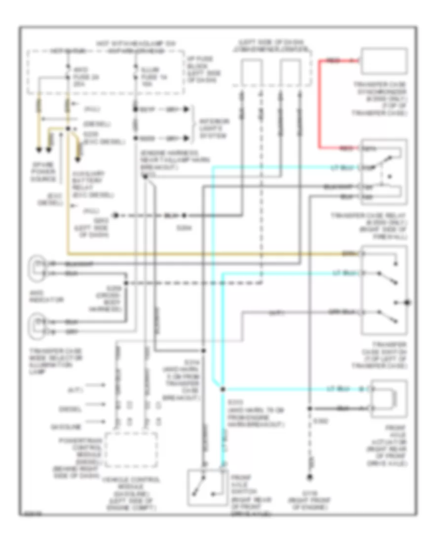
Transfer Case Wiring Diagram, without Electronic Shift Control for Chevrolet Tahoe 1997
List of elements for Transfer Case Wiring Diagram, without Electronic Shift Control for Chevrolet Tahoe 1997:
- (4wd harn, 79 cm from engine harn breakout)
- (a/t)
- (all)
- (diesel)
- (engine harness, near taillamp harn breakout) s111
- (exc diesel)
- (left side of dash) convenience center
- (right rear of front drive axle)
- 4wd fuse 24 25a
- 4wd indicator
- 87a
- Auxiliary battery relay (exc diesel)
- Diesel
- Front axle actuator (right rear of front drive axle)
- Front axle switch
- G119 (right front of engine)
- G202 (left side of dash)
- Gasoline
- Hot in run
- Hot with headlamp sw in park or head
- I/p fuse block (left side of dash)
- Illum fuse 14 10a
- Interior lights system
- Powertrain control module (diesel) (behind right side of dash)
- Red
- S204
- S217
- S235 (exc diesel)
- S253
- S259 (cross- body harness)
- S302
- S313
- S314 (4wd harn, 5 cm from transfer case breakout)
- Spare power source
- Transfer case mode selector illumination lamp
- Transfer case relay (k3500 only) (right side of firewall)
- Transfer case switch (top left of transfer case)
- Transfer case synchronizer (k3500 only) (top of transfer case)
- Vehicle control module (gasoline) (left side of engine compt)
6.5L
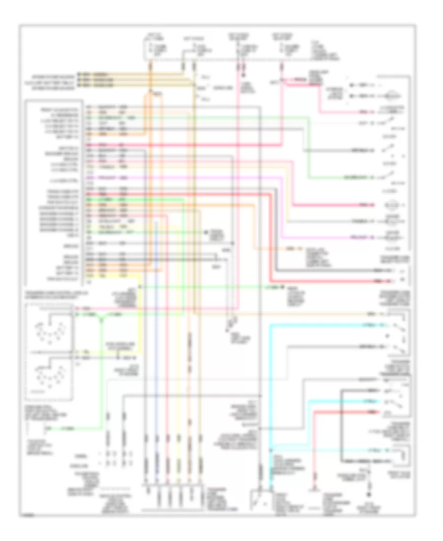
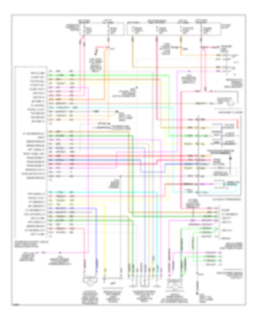
6.5L (VIN S), Transmission Wiring Diagram, 4L80-E for Chevrolet Tahoe 1997
List of elements for 6.5L (VIN S), Transmission Wiring Diagram, 4L80-E for Chevrolet Tahoe 1997:
- (2wd only)
- (4wd only)
- (i/p harn, 4 cm from engine harn break-out)
- 1-2 shift sol
- 1-2 shift solenoid
- 2-3 shift sol
- 2-3 shift solenoid
- 4wd low signal in
- A/t iss sens hi in
- A/t iss sens in
- A/t iss sens lo in
- A/t iss sensor out
- A12
- Accelerator pedal position module (part of accelerator pedal)
- App 1 5v ref
- App 1 signal in
- App 2 5v ref
- App 2 signal in
- App 3 5v ref
- App 3 signal in
- Automatic transmission
- Automatic transmission input shaft speed sensor (left front of transmission)
- B10
- B12
- Battery in
- Brake fuse 18 10a
- Brake switch assembly (on brake pedal bracket)
- Brake switch in
- C11
- C12
- C13
- C14
- C15
- Class ii data
- D11
- D12
- D13
- Data link connector (under left side of dash)
- Ecm 1 fuse 20a
- Ecm b fuse 20a
- Ect sensor in
- Engine coolant temp sensor (near thermostat housing)
- Front wheel lock
- Fuel pump & oil press switch/ sender & fuel pump relay
- G120 (right top of cylinder head)
- Gauges fuse 4 10a
- Ground
- Hot at all times
- Hot in run
- Hot in run or start
- Hot in run, bulb test or start
- I/p fuse block
- Ignition in
- Instrument cluster
- Malfunction indicator lamp
- Mil control
- Pcm ground
- Pcs sol hi out
- Pcs sol lo out
- Pnk
- Power
- Powertrain control module (right side of dash near blower motor)
- Press ctrl
- Red
- S101
- S103
- S140 (engine sensor harness)
- S150 (engine harness, 13 cm from bpmv harness break-out)
- S152 (engine harn, 4 cm from i/p break-out)
- S211
- S213
- S220 (i/p harn, 12 cm from brake switch connector)
- S299
- Sensor ground
- Solenoid
- Stop/haz fuse 1 20a
- Stoplamp switch in
- Tan
- Tcc pwm
- Tcc pwm sol
- Tft sensor in
- Trans fluid temp sensor
- Trans fuse 20 10a
- Trans range "a"
- Trans range "b"
- Trans range "c"
- Trans range pressure switch assembly
- Trans range switches
- Transfer case & axle switches
- Transfer case circuit
- Turn/ hazard switch & chime module
- Underhood fuse/relay center
- Vehicle speed sensor (on transmission-2wd) (on transfer case-4wd)
- Vehicle speed sensor (vss) adaptor (4wd only)
- Vehicle speed sensor buffer (right side of dash)
- Vss hi in
- Vss in
- Vss lo in
- Vss out
Transfer Case Wiring Diagram, with Electronic Shift Control for Chevrolet Tahoe 1997
List of elements for Transfer Case Wiring Diagram, with Electronic Shift Control for Chevrolet Tahoe 1997:
- (all)
- (behind right side of dash)
- (diesel)
- (gasoline)
- (gasoline) s162 (diesel) s107
- +8v ref
- 2 hi indic ctrl
- 2 hi select sw in
- 2-hi ind
- 2-hi sw
- 4 hi indic ctrl
- 4 hi select sw in
- 4 lo indic ctrl
- 4 lo sw
- 4 low select sw in
- 4-hi ind
- 4-hi sw
- 4-lo ind
- 4wd fuse 24 25a
- 5v reference
- 87a
- Auxiliary battery relay
- Battery in
- C10
- C11
- C12
- C13
- C14
- C15
- C16
- Channel a
- Channel b
- Channel c
- Channel p
- D10
- D11
- D12
- D13
- D14
- D15
- D16
- Data link connector (partial) (under left side of dash)
- Diagnostics enable
- Diesel
- Encoder channel a
- Encoder channel b
- Encoder channel c
- Encoder channel p
- Encoder ground
- Front axle actuator
- Front axle switch
- Front axle switch (right rear of front drive axle)
- G119 (right front of engine)
- G202 (left side of dash)
- Gasoline
- Gauges fuse 4 10a
- Gnd
- Ground
- Headlamp/ panel dimmer switch
- Hot at all times
- Hot in run
- Hot in run or start
- I/p fuse block (under left side of dash)
- Ignition in
- Illumination lamp
- Interior lights system
- Park/neutral position switch (on left side, center of transmission)
- Pnk
- Pnp switch out
- Powertrain control module (diesel)
- Rear liftgate window release circuit
- Red
- S111 (engine harn, near tail- lamp harness break-out)
- S162 (gasoline) s107 (diesel)
- S204
- S213
- S235
- S270
- S271 (i/p harness, 5 cm inside crossbody harness)
- S298
- S302
- S313 (4wd harness, 79 cm from engine harness break-out)
- S314 (4wd harn, approx 5 cm from transfer case relay breakout from axle switch)
- Spare power source
- Tcase fuse 2 20a
- Tcc/stop lamp switch (top of brake pedal)
- Trans case mtr
- Trans- mission circuit
- Transfer case control module (steering column bracket)
- Transfer case encoder (left side center of transfer case)
- Transfer case encoder motor (left side of transfer case)
- Transfer case relay (1-ton vehicles only) (right side of firewall)
- Transfer case select switch
- Transfer case switch (top left of transfer case)
- Transfer case synchronizer (top of transfer case)
- Turn b/u fuse 16 20a
- Turn signal switch
- Vehicle control module (gasoline) (left side of engine compt)
- Vss in
Transfer Case Wiring Diagram, without Electronic Shift Control for Chevrolet Tahoe 1997
List of elements for Transfer Case Wiring Diagram, without Electronic Shift Control for Chevrolet Tahoe 1997:
- (4wd harn, 79 cm from engine harn breakout)
- (a/t)
- (all)
- (diesel)
- (engine harness, near taillamp harn breakout) s111
- (exc diesel)
- (left side of dash) convenience center
- (right rear of front drive axle)
- 4wd fuse 24 25a
- 4wd indicator
- 87a
- Auxiliary battery relay (exc diesel)
- Diesel
- Front axle actuator (right rear of front drive axle)
- Front axle switch
- G119 (right front of engine)
- G202 (left side of dash)
- Gasoline
- Hot in run
- Hot with headlamp sw in park or head
- I/p fuse block (left side of dash)
- Illum fuse 14 10a
- Interior lights system
- Powertrain control module (diesel) (behind right side of dash)
- Red
- S204
- S217
- S235 (exc diesel)
- S253
- S259 (cross- body harness)
- S302
- S313
- S314 (4wd harn, 5 cm from transfer case breakout)
- Spare power source
- Transfer case mode selector illumination lamp
- Transfer case relay (k3500 only) (right side of firewall)
- Transfer case switch (top left of transfer case)
- Transfer case synchronizer (k3500 only) (top of transfer case)
- Vehicle control module (gasoline) (left side of engine compt)