TRANSMISSION
A/T Wiring Diagram for Chevrolet Venture LS 2005

List of elements for A/T Wiring Diagram for Chevrolet Venture LS 2005:
- (fuel injector harn, near breakout for c102)
- (in engine harness, near breakout for powertrain control module)
- 1-2 shift sol
- 2-3 shift sol
- 2-3 shift sol valve
- 5v reference a
- A/t sensor hi
- A/t sensor lo
- Automatic transmission
- Automatic transmission fluid pressure manual valve position switch
- Automatic transmission fluid temperature sensor
- Automatic transmission input shaft speed sensor
- Battery in
- Data link connector (dlc) (below steering column, on knee bolster)
- Ecm sense fuse 10a
- Ect sensor in
- Engine coolant temperature (ect) sensor (on top left rear of engine)
- G113 (in engine compt, left of starter)
- Hot at all times
- Hot in run, bulb test or start
- I/p fuse block (right side of dash, in right front door opening)
- Ign
- Ign 0
- Ign 1
- Ign 1 fuse 10a
- Ignition in
- Instrument panel cluster
- Logic
- Manifold absolute pressure (map) sensor (on top right side of engine)
- Map sensor return
- Mil ctrl
- Pc sol hi
- Pc sol lo
- Pcm ground
- Pcm/ passkey/ cluster fuse 10a
- Pnk
- Power distribution system
- Powertrain control module (pcm) (secured in air cleaner assembly, left front of engine compt)
- Pressure control sol valve
- Red
- S106
- S106 (in engine harness, near breakout for powertrain control module)
- S110
- S115
- S209 (in dash harness, near breakout for security indicator light)
- S210 (in dash harness, near breakout for security indicator light)
- Ser class ii data
- Service engine soon ind
- Sp205
- Stoplamp switch (mounted on top of brake pedal support)
- Tan
- Tcc fuse 10a
- Tcc pwm sol
- Tcc pwm sol valve
- Tcc rel switch
- Tcc release in
- Tcc/ brake switch
- Tcc/brake sw in
- Tft sensor gnd
- Tft sensor in
- Throttle position (tp) sensor (on throttle body assembly)
- Tp sensor in
- Tp sensor return
- Tr sw in-a
- Tr sw in-b
- Tr sw in-c
- Tr sw in-p
- Transmission internal mode switch (ims)
- Underhood fuse block (above battery)
- Vehicle speed sensor (vss) (mounted to right side of transaxle)
- Vss hi (signal)
- Vss lo (ground)
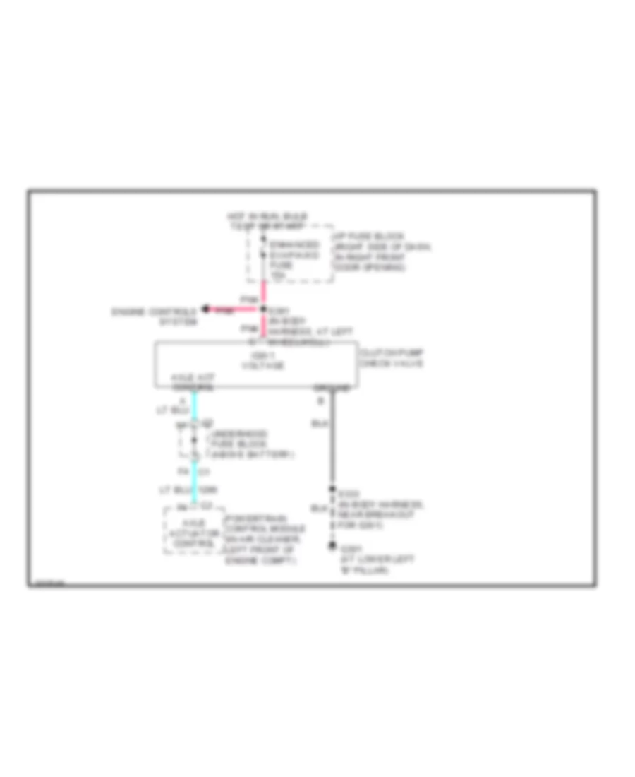
Rear Differential Lock Wiring Diagram for Chevrolet Venture LS 2005
List of elements for Rear Differential Lock Wiring Diagram for Chevrolet Venture LS 2005:
- "b" pillar)
- Axle act control
- Axle actuator control
- Clutch pump check valve
- Engine controls system
- Enhanced evap/awd fuse 15a
- F4 c1
- G301 (at lower left
- Ground
- Hot in run, bulb test or start
- I/p fuse block (right side of dash, in right front door opening)
- Ign 1 voltage
- Near breakout for g301)
- Pnk
- Powertrain control module (in air cleaner, left front of engine compt)
- S391 (in body harness, at left wheelwell)
- Underhood fuse block (above battery)