TRANSMISSION
5.9L
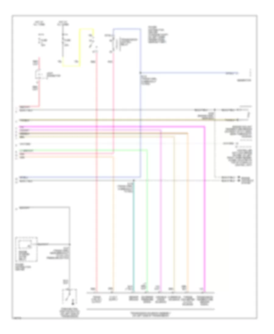
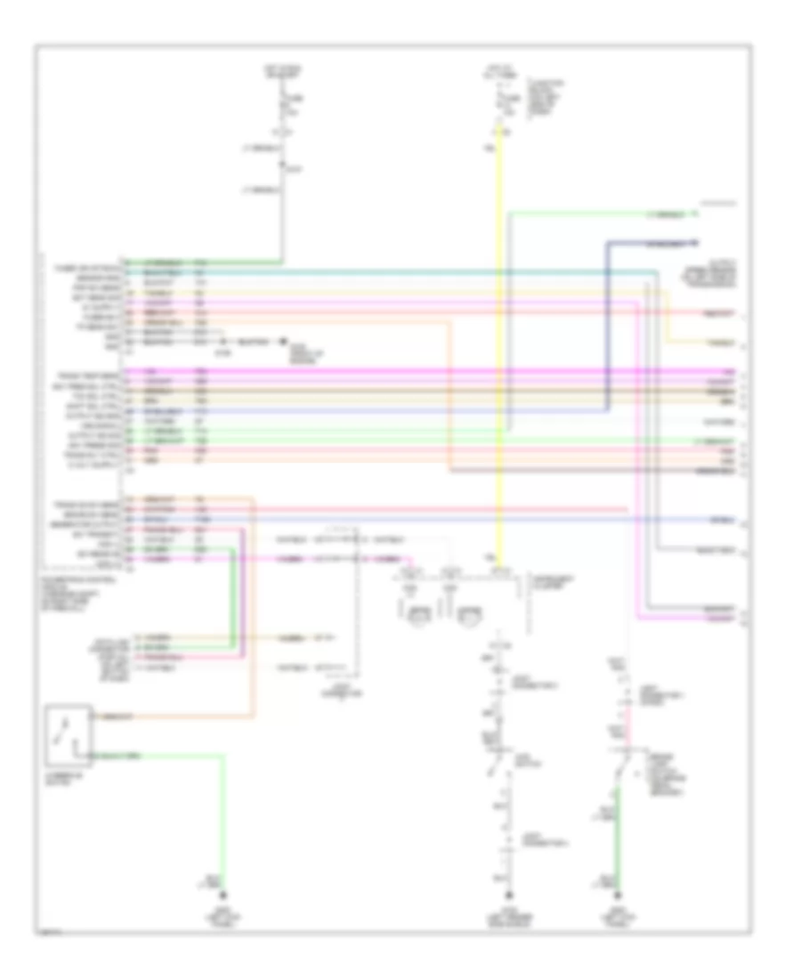
5.9L 24-Valve Diesel, A/T Wiring Diagram (1 of 2) for Dodge Cab & Chassis R2500 2001

List of elements for 5.9L 24-Valve Diesel, A/T Wiring Diagram (1 of 2) for Dodge Cab & Chassis R2500 2001:
- (eng harn, near breakout to a/c low pressure switch)
- (not used)
- (primary battery body ground) g115
- (trans harn, in breakout to pdc)
- (trans harn, in breakout to pdc)
- 4wd switch
- 4x4 ind
- A14
- Brake lamp switch (on brake pedal bracket)
- Brake sw sens
- Ccd (+)
- Ccd (-)
- Ckp sens sig
- D20
- D21
- D220
- Data link connector (partial) (on left bottom of dash)
- Ect sens sig
- Engine control module (on left side of engine, behind fuel filter)
- F18
- Fuse 10a
- Fused (b+)
- Fused b(+)
- Fused ign (st/run)
- G100 (left fender side shield)
- G200 (left kick panel)
- Generator output
- Gnd
- Gov pres sol ctrl
- Gov press sig
- Hot at all times
- Hot in run or start
- Instrument cluster
- Joint connector 1 (in pdc)
- Joint connector 3
- Joint connector 4
- Joint connector 7
- Junction block (on left end of dash)
- K104
- K22
- K24
- K30
- K54
- K88
- Od ind
- Output speed sensor (on left side of transmission)
- Output ss gnd
- Output ss sig
- Overdrive switch
- Pnk
- Pnp sw sens
- Powertrain control module (in engine compt, on right side of firewall)
- S107
- S111 (trans harn, near breakout to a/c low pressure switch)
- S126
- S161
- S167
- S171
- S172
- S173
- S174
- S175
- Sci receive
- Sci transit
- Sci transmit
- Sensor gnd
- Sensor ground
- Shift sol ctrl
- T125
- T13
- T14
- T25
- T41
- T54
- T60
- Tcc sol ctrl
- Tp sens sig
- Tps sens sig
- Trans od sw sens
- Trans rly ctrl
- Trans temp sens
- V40
- Vss signal
- Z12
5.9L 24-Valve Diesel, A/T Wiring Diagram (2 of 2) for Dodge Cab & Chassis R2500 2001
List of elements for 5.9L 24-Valve Diesel, A/T Wiring Diagram (2 of 2) for Dodge Cab & Chassis R2500 2001:
- Controller anti-lock brake (rwabs: on left front inner fender, 4wabs: mounted on top of hydraulic control unit)
- Engine controls system
- Engine coolant temperature sensor (on front of cyl head, near thermostat housing)
- Engine starter motor relay
- Fuse 20a
- Fuse i 20a
- Generator
- Governor pressure signal
- Hot at all times
- Joint connector
- Overdrive solenoid
- Park/neutral position switch (on left side of transmission)
- Pnk
- Power distribution center
- Power distribution center (in engine compt, on left inner fender panel, near battery)
- Red
- S116 (trans harn, in breakout to pdc)
- S127 (trans harn, near breakout to a/c low pressure switch)
- S165 (engine harn, near ecm)
- S179 (trans harn, in breakout to pdc)
- Sensor ground
- Torque converter clutch solenoid
- Trans ctrl rly output
- Transmission control relay
- Transmission solenoid assembly (on left side of transmission)
- Transmission temperature sensor signal
- Variable force solenoid
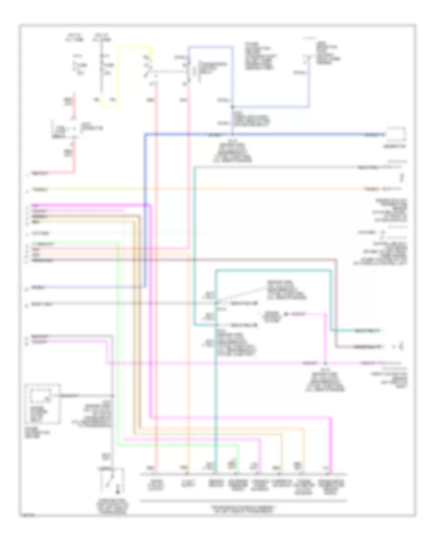
5.9L, A/T Wiring Diagram (1 of 2) for Dodge Cab & Chassis R2500 2001
List of elements for 5.9L, A/T Wiring Diagram (1 of 2) for Dodge Cab & Chassis R2500 2001:
- (on left bottom of dash)
- 4wd switch
- 4x4 ind
- A14
- Brake lamp switch (on brake pedal bracket)
- Brake sw sens
- Ccd (+)
- Ccd (-)
- D20
- D21
- Data link connector (partial)
- Ect sens sig
- F18
- Fuse 10a
- Fused b(+)
- Fused ign (st/run)
- G100 (left fender side shield)
- G105 (front of engine)
- G200 (left kick panel)
- Generator output
- Gnd
- Gov pres sol ctrl
- Gov press sig
- Hot at all times
- Hot in run or start
- Instrument cluster
- Joint connector
- Joint connector 1 (in pdc)
- Joint connector 3
- Joint connector 4
- Junction block (on left end of dash)
- K22
- K30
- K54
- K88
- Od ind
- Output speed sensor (on left side of transmission)
- Output ss gnd
- Output ss sig
- Overdrive switch
- Pnk
- Pnp sw sens
- Powertrain control module (in engine compt, on right side of firewall)
- S107
- S126
- Sci receive
- Sci transmit
- Sensor gnd
- Shift sol ctrl
- T125
- T13
- T14
- T25
- T41
- T54
- T60
- Tcc sol ctrl
- Tp sens sig
- Trans od sw sens
- Trans rly ctrl
- Trans temp sens
- V40
- Vss signal
- Z12
5.9L, A/T Wiring Diagram (2 of 2) for Dodge Cab & Chassis R2500 2001
List of elements for 5.9L, A/T Wiring Diagram (2 of 2) for Dodge Cab & Chassis R2500 2001:
- (engine harn, 3.9l, 5.2l & 5.9l: near breakout to fuel injectors; 8.0l: rear of engine)
- 2 (or 6)
- Controller anti- lock brake (rwabs: on left front inner fender, 4wabs: mounted on top of hydraulic control unit)
- Engine controls system
- Engine coolant temperature sensor (in water jacket, at front of intake manifold)
- Engine starter motor relay
- Fuel pump relay
- Fuse 20a
- Fuse i 20a
- Generator
- Governor pressure signal
- Hot at all times
- Joint connector
- Leak detection pump (on right front inner fender)
- Overdrive solenoid
- Park/neutral position switch (on left side of transmission)
- Pnk
- Power distribution center
- Power distribution center (in engine compt, on left inner fender panel, near battery)
- Red
- S116 (engine harn, 3.9l, 5.2l & 5.9l: near breakout to fuel injectors; 8.0l: rear of engine)
- S118
- S119 (engine harn, 3.9l, 5.2l & 5.9l: near breakout to fuel injectors; 8.0l: rear of engine)
- S127 (engine harn, 3.9l, 5.2l & 5.9l: on top of transmission; 8.0l: near breakout to transmission)
- Sensor ground
- Throttle position sensor (on throttle body)
- Torque converter clutch solenoid
- Trans ctrl rly output
- Transmission control relay
- Transmission solenoid assembly (on left side of transmission)
- Transmission temperature sensor signal
- Variable force solenoid
8.0L
8.0L, A/T Wiring Diagram (1 of 2) for Dodge Cab & Chassis R2500 2001
List of elements for 8.0L, A/T Wiring Diagram (1 of 2) for Dodge Cab & Chassis R2500 2001:
- (on left bottom of dash)
- 4wd switch
- 4x4 ind
- A14
- Brake lamp switch (on brake pedal bracket)
- Brake sw sens
- Ccd (+)
- Ccd (-)
- D20
- D21
- Data link connector (partial)
- Ect sens sig
- F18
- Fuse 10a
- Fused b(+)
- Fused ign (st/run)
- G100 (left fender side shield)
- G105 (front of engine)
- G200 (left kick panel)
- Generator output
- Gnd
- Gov pres sol ctrl
- Gov press sig
- Hot at all times
- Hot in run or start
- Instrument cluster
- Joint connector
- Joint connector 1 (in pdc)
- Joint connector 3
- Joint connector 4
- Junction block (on left end of dash)
- K22
- K30
- K54
- K88
- Od ind
- Output speed sensor (on left side of transmission)
- Output ss gnd
- Output ss sig
- Overdrive switch
- Pnk
- Pnp sw sens
- Powertrain control module (in engine compt, on right side of firewall)
- S107
- S126
- Sci receive
- Sci transmit
- Sensor gnd
- Shift sol ctrl
- T125
- T13
- T14
- T25
- T41
- T54
- T60
- Tcc sol ctrl
- Tp sens sig
- Trans od sw sens
- Trans rly ctrl
- Trans temp sens
- V40
- Vss signal
- Z12
8.0L, A/T Wiring Diagram (2 of 2) for Dodge Cab & Chassis R2500 2001
List of elements for 8.0L, A/T Wiring Diagram (2 of 2) for Dodge Cab & Chassis R2500 2001:
- (engine harn, 3.9l, 5.2l & 5.9l: near breakout to fuel injectors; 8.0l: rear of engine)
- 2 (or 6)
- Controller anti- lock brake (rwabs: on left front inner fender, 4wabs: mounted on top of hydraulic control unit)
- Engine controls system
- Engine coolant temperature sensor (in water jacket, at front of intake manifold)
- Engine starter motor relay
- Fuel pump relay
- Fuse 20a
- Fuse i 20a
- Generator
- Governor pressure signal
- Hot at all times
- Joint connector
- Leak detection pump (on right front inner fender)
- Overdrive solenoid
- Park/neutral position switch (on left side of transmission)
- Pnk
- Power distribution center
- Power distribution center (in engine compt, on left inner fender panel, near battery)
- Red
- S116 (engine harn, 3.9l, 5.2l & 5.9l: near breakout to fuel injectors; 8.0l: rear of engine)
- S118
- S119 (engine harn, 3.9l, 5.2l & 5.9l: near breakout to fuel injectors; 8.0l: rear of engine)
- S127 (engine harn, 3.9l, 5.2l & 5.9l: on top of transmission; 8.0l: near breakout to transmission)
- Sensor ground
- Throttle position sensor (on throttle body)
- Torque converter clutch solenoid
- Trans ctrl rly output
- Transmission control relay
- Transmission solenoid assembly (on left side of transmission)
- Transmission temperature sensor signal
- Variable force solenoid